background image

12

FUNCTIONS COMMON TO ALL MODELS

Lock  function  (

): 

this  function  prevents  the  hob  from  being  switched  on  accidentally  (childproof

safety device). To activate it, the  

sensor must be pressed for about three seconds (the warning light

comes on). It is not possible to operate the heated areas when   

is active. While the heaters are still

working, it is possible to switch off the heating areas in 

. This function is deactivated by pressing the

sensor for two seconds, for all configurations. 

RESIDUAL HEAT

Every plate has a device to indicate the presence of residual heat. After any plate has been switched off,

a flashing light may be shown on 

the display. This signal indicates that the particular cooking area is

still very hot. It is possible to start cooking food when the light  

is flashing, reactivating the heating

element required.

SWITCHING OFF THE HEATING ELEMENTS

When the plates are switched off, the operating power display indicates 

0

.

The plate will be automatically deactivated 5 seconds after the display indicates 0. If the plates are hot,

the residual heat indicator will appear after they are switched off 

.

SWITCHING OFF THE HOB

The  hob  is  switched  off  by  keeping  the 

symbol  pressed  for  one  second,  even  with  the  plates  in

operation. All the plates will be deactivated and the hob will be switched off completely. If the plates are

hot, the residual heat indicator will appear a few seconds after the hob 

is switched off.

If the heater is working in Low-temp Function, the levelassumed is 3.

USE

If  the  power  level  is  not  changed  during  a  preset  time,

the corresponding heater turns off automatically.

The  maximum  time  a  heater  can  stay  on,  depends  on

the selected cooking level.

AUTOMATIC SAFETY OFF

Power 

level

Max. time on 

(hours)

1

10

2

5

3

5

4

4

5

3

6

2

7

2

8

2

9

1

Summary of Contents for PCZ VTC 30

Page 1: ...ed The manufacturer declines all responsability for improper installation USE INSTALLATION AND MAINTENANCE INSTRUCTIONS FOR ELECTRICAL BUILT IN HOT PLATES The manufacturer is not responsible for any t...

Page 2: ...or oil can be dangerous and may result in fire NEVER try to extinguish a fire with water but switch off the appliance and then cover flame e g with a lid or a fire blanket WARNING Danger of fire do no...

Page 3: ...he controls on the front panel from a minimum of 1 to a maximum of 9 1 Radiant electric heating element Hi light 18 0 cm of 1800 W 2 Radiant electric heating element Hi light 14 0 cm of 1200 W 7 Touch...

Page 4: ...356 MODEL PT1358 1 ON OFF button cooking zone 2 Capacity level display 0 9 4 Safety lock button 5 Button increase power level 6 Button decrease power level 1 ON OFF button 2 Capacity level display 0 9...

Page 5: ...ing from improper incorrect or unreasonable use During and immediately after operation some parts of the cook top are very hot avoid touching them If the ceramic glass hob is not cleaned immediately t...

Page 6: ...if residual heat exists Zone will be OFF If any cooking stage is in position 0 this display will switch OFF automatically after 10 seconds and the zone OFF sequence will sound If there is residual he...

Page 7: ...2 sec Short beep will be heard and displays will show L letter during 2 sec Then any time when a key will be touched displays will show L during 2 sec heating remains at the same state To deactivate C...

Page 8: ...lays we would follow seeing these power levels number Step 3 But really the heaters would have a Ton cycle totally different Heater 1 and 2 would be working with a real Ton cycle of power level 7 heat...

Page 9: ...f Ft FalloOverTemp Touch NTc Error App Off Fc FalloEepromChecksum Eeprom Checksum Error App Off FH FalloPWMfreq Security Key Control Error App Off FC FalloPWMLevel Security Key Control Error App Off F...

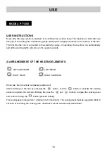
Page 10: ...ral seconds 2 ARRANGEMENT OF THE HEATING ELEMENTS LEFT ANTERIOR LEFT REAR RIGHT REAR RIGHT ANTERIOR When idle the hob will be completely switched off After switching on the hob by pressing the button...

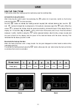
Page 11: ...y fixed on display for 10 seconds Fig A and B during which time the desired power level must be selected between 1 and 8 Confirm it using the button pressed initially After this time a beep sounds and...

Page 12: ...reactivating the heating element required SWITCHING OFF THE HEATING ELEMENTS When the plates are switched off the operating power display indicates 0 The plate will be automatically deactivated 5 seco...

Page 13: ...be exposed to substancial risks Display F and numbers If F and numbers appears in the display your unit has detected a fault The following table list actions you can take to correct the problem Heate...

Page 14: ...d auto check It disap pears when auto check return to secure value If error persist call after sale service FA Security software error This error is a software auto check It disappears when auto check...

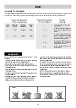
Page 15: ...erence for a correct use please look at fig 1 and remind switch on the electricity only after having placed the pot on the cooking zone Use pots and pans with flat solid bottoms Use pots with the same...

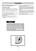
Page 16: ...the hob It is very important to clean the surface soon after every use when the glass is still tepid Do not use metallic sponges powder abrasives or corrosive sprays Depending on the dirty level we r...

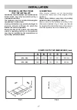
Page 17: ...or regulating devices on the appliance may only be modified by the manufacturer or by his duly authorized dealer 5 INSERTING After having cleared out all the packing components make sure of the integr...

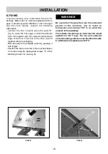
Page 18: ...hob The ends of the strip must fit together without overlapping Stick the putty to the hotplate uniformly pressing it with fingers Position the hob in the hole in the unit and fasten it in place using...

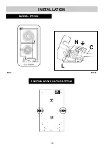
Page 19: ...19 INSTALLATION FIG 7 MODEL PT1356 POSITION HOOKS ON THE BOTTOM FIG 8...

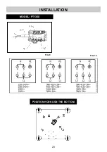
Page 20: ...INSTALLATION FIG 10 20 MODEL PT1358 POSITION HOOKS ON THE BOTTOM FIG 9...

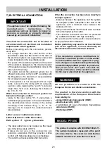
Page 21: ...dangerous overheatings The outlet must be accessible after the built in When the connection has been done directly to the input system interpose between the appliance and the system an onnipolar switc...

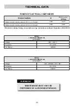
Page 22: ...sent a scheme with the characteristics of the components keeping in mind the contemporaneousness factor TYPE AND SECTION OF THE POWER CABLES FOR 4 5 HEATING ELEMENTS TYPE AND SECTION OF THE POWER CABL...

Page 23: ...t 1800 188 5 ECelectric cooking Energy consumption per kg calculated according to Regulation EU 66 2014 MAINTENANCE MUST ONLY BE PERFORMED BY AUTHORISED PERSONS MODEL 2 HEATING ELEMENTS 30 2 HI LIGHT...

Page 24: ...quired may only be carried out by qualified personnel with the utmost care and attention For this reason always contact your Dealer or your nearest After Sales Centre whenever repairs or adjustments a...

Reviews: