background image

 18


7.2  Information  on  Exhaust  Air 
Ducting


The  planning  and  design  of  extractor  ducting  has  a 
significant  influence  on  the  airflow  rate  and  the 
noise level of the cooker hood. This is because each 
component  in  the  ducting  introduces  counter 
pressure  (frictional  resistance),  which  leads  to  a 
reduction in the airflow rate in the cooker hood and 
increases the level of noise.


The  frictional  resistance  within  the  ducting  is 
dependent on a number of factors:


− 

Cross section of the exhaust air ducting.


− 

Length of the exhaust air ducting.


− 

Bends/curves in the exhaust air ducting.


− 

Material  and  type  of  ducting  (the  material 
must  also  be  approved  for  use  with  a 
cooker  hood  in  accordance  with  fire 
prevention regulations).


7.3  Cross  Section  of  the  Exhaust 
Air Ducting


The cross section of the ducting must be adapted to 
match  the  airflow  rate  of  the  cooker  hood  and  the 
ducting routing  (length and design). A  cross section 
that  is  too  narrow  will  result  in significant  losses in 
the  airflow  rate  and  increase  noise  level.  The 
ventilation  performance  of  the  cooker  hood  is  the 
key factor for determining the ducting cross section. 
The more powerful the ventilation performance, the 
greater the ducting cross section must be.


As  a  rule,  the  larger  the  cross  section,  the  less 
counter pressure is created in the ducting.


The  following  exhaust  air  ducting  specifications 
serve as a guide:


Ø125mm for a ventilation performance of >400m

3

/h


Ø150mm for a ventilation performance of <400m

3

/h


Any  reduction  in  the  cross  section  of  the  ducting 
must be avoided.


This  would  give  rise  to  turbulence,  which  would 
generate  a  high  amount  of  counter  pressure.  The 
more  rapid  airflow  speed  associated  with  a 
narrowing  in  the  cross  section  will  also  cause  the 
noise level to increase.


TIP


It  is  only  possible  to  achieve  a  high  airflow  volume 
and  low  noise  level  by  using  extractor  ducting  that 
provides low  resistance. Always use  where possible 
rigid ducting equivalent to 150mm.


Summary of Contents for DIAMOND 60

Page 1: ...Diamond Flex Hob Extractor Installation User Instructions Please read these instructions carefully before installing and operating this appliance ...

Page 2: ...el for the Zone 8 9 5 4 3 Fast Boil Booster Function 9 5 4 4 Bridge Function 9 10 5 5 Setting Hob ECO Power Limit 10 11 5 5 1 For Selecting a New Power Limit 11 5 5 2 The Sequence to Finish Recording the New Hob Power Limit 11 5 5 3 To Finish Without Recording Changes 11 5 6 Power Management for ECO Hob 11 5 7 Key Lock 11 5 8 Protection From Accidental Activation of Keys 11 5 9 Zone Auto Switch Of...

Page 3: ...ion on Exhaust Air Ducting 18 7 3 Cross Section of the Exhaust Air Ducting 18 7 4 Exhaust Material Ducting Shape 19 7 5 Length of the Exhaust Ducting Curves Bends 20 21 7 6 Recirculating Option 22 8 Electrical Connection 22 23 9 Troubleshooting 23 9 1 Displaying Special Statuses 23 24 9 2 Errors Alarms 24 10 Maintenance Cleaning 25 11 Technical Data 26 12 Energy Label 27 13 Dimensions 28 ...

Page 4: ...carrying out any cleaning or maintenance operation make sure in advance that the appliance is isolated from the mains electricity supply Incorrect installation or faulty maintenance not conforming to the requirements set out in this booklet can cause harm to people animals or property In such cases Air Uno is absolved from any civil or criminal responsibility This product complies with EU Directiv...

Page 5: ...scretion either repair or replace the goods Free of Charge including any carriage costs This is based on the following conditions 1 The product has been fitted installed as per our instructions 2 The product has been used for normal domestic purposes only and in accordance with the manufacturer s operating and maintenance instructions 3 The product has been serviced maintained repaired taken apart...

Page 6: ...4 Extractor Operation The extractor is operated by a capacitive glass slider When first turned on the extractor will always turn on at speed 2 V2 Intensive speed V6 is set for a maximum of 5 minutes and then the hood returns to V3 The Timer function is 10 minutes long and it is displayed with a flashing LED it doesn t turn off when the speed changes Timer function and intensive speed can be activa...

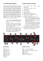
Page 7: ...ation process approx 3s any cooker hood or other lighting can be switched on as normal and will not affect the operation of the touch control 5 2 Basic Control Functions The control allows different layout configurations Full induction hobs with 3 or 4 zones Keylock function Fast boil function Stop Go function Independent timer for each zone Indication of residual heat for each zone Thermal contro...

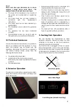
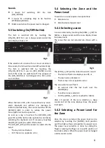
Page 8: ...KEY will be locked to switch ON the hob if The key lock is activated Or if there is an appliance error 5 4 Selecting the Zone and the Power Level To switch on a zone requires two operations Select a zone Select a desired power level 5 4 1 Selecting a zone A zone is selected by touching the ZONE_n_KEY for 160ms a beep sounds and the zone display shows the power level The zones that are not selected...

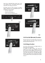
Page 9: ...e zone will work at booster power level for 10 minutes After these 10 minutes a beep sounds and the zone will return to level 9 5 4 4 Bridge Function Two zones can be joined by the bridge function to heat longer pans and griddles To enable the bridge function first touch the selection key of one of the bridgeable zones and then touch the other bridgeable zone selection key The power level of the f...

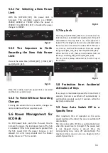
Page 10: ...nction select any of the bridged zones while the bridge LEDs are blinking touch any of the bridged zone selection keys again Fig 9 5 5 Setting Hob ECO Power Limit The hobs maximum power limit is 7200W This power limit can be reduced by the user to 2800W 3500W or 6000W The sequence to set a new how power limit is During the first 30 seconds after plugging in the appliance The keylock has to be unlo...

Page 11: ...K_KEY for 1 second the key lock function is activated and deactivated If the LED associated to the key lock is on the keyboard is locked The locking function can be activated when the zones are on or when the hob is off If the hob is on the key lock function locks all the keys except the general ON_OFF_KEY and the KEYLOCK_KEY When the hob is off the key lock function locks all the keys including t...

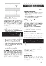
Page 12: ...n off anticlockwise A new segment is switched on off every T_320ms Fig 17 To deactivate the stop function If the STOP_GO_KEY is touched for more than 120ms a beep sounds and the zones power level is restored or If the hob is stopped for more than 10 minutes the hob is switched off automatically 5 11 Operating the Timer It is possible for the user to set a switch off time for all zones at any power...

Page 13: ...sounds for one minute The timer alarm can be cancelled by the user at anytime by pressing any key of the touch control Switching Off the Timer To cancel operation of the timer select the time value of 00 using the TIMER key or pressing the TIMER and TIMER keys at the same time More than one Zone Timed When more than one zone is timed the timer displays will show the timer that is going to elapse f...

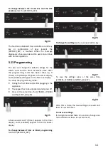
Page 14: ...the first zone display To call up the programming mode During the first 30 seconds after plugging in the appliance The keypad has to be unlocked and all zones off Press at the same time the TIMER TIMER and the STOP_GO_KEY Fig 25 A beep sounds and Ti Timer appears in the timer display and 1 enabled appears in the first heater display To change between Timer or Slider programming touch the KEYLOCK_K...

Page 15: ...y A reduced function of the pacemaker is unlikely If in doubt contact the manufacturer of your medical device or your doctor Do not make any changes to the appliance Whenever possible clean the hob after every use Clean the hob only after it has cooled down When cleaning only use non abrasive cleaning agents to prevent scratching and abrasion on the surface Always lift the cookware to prevent scra...

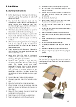
Page 16: ...n the worktop We recommend using silicone under the edge of the hob to seal the product to the worktop 7 Ducting When the extractor is used in the duct version it must be connected to an outside wall vent Ø150mm round or 220x90mm rectangular ducting must be used Ducting with a smaller diameter could cause airflow issues and invalidate the warranty 7 1 Ducting Assembly In a 600mm cupboard the back ...

Page 17: ...into one another as shown in Fig 29 Fig 29 02TP822 D 02TP824 D 02TP820 D 02TP820 D 02TP823 D 02TP823 D Min 40mm Minimum Cupboard Depth 600mm Max 490mm Max 490mm Max 490mm 510mm 600mm 50mm 244mm 02TP823 D 02TP820 D 02TP823 D 02TP824 D 100mm plinth 391mm ...

Page 18: ...outing length and design A cross section that is too narrow will result in significant losses in the airflow rate and increase noise level The ventilation performance of the cooker hood is the key factor for determining the ducting cross section The more powerful the ventilation performance the greater the ducting cross section must be As a rule the larger the cross section the less counter pressu...

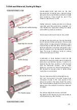
Page 19: ... the flapping film generates noise This type of ducting is prone to crushing which will create a poor air flow A distinction is made between round and flat channels Flat channels are often used in practice for both visual and technical reasons It used to be believed that the flow conditions in flat channels were less favourable However this no longer applies as a general rule Recent developments i...

Page 20: ...s with largest possible radius are advisable The smaller the bend radius the greater the counter pressure Corners at right angles should also be avoided if possible because these lead to even greater pressure losses and therefore a loss of performance TIP The following rule of thumb applies for good duct routing The distance between two bends should be at least 1m although 1 5m is better Optimal f...

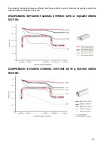
Page 21: ...different duct types and flat channels indicates the extent to which the material used can influence airflow loss COMPARISON BETWEEN CHANNEL SYSTEMS WITH A SQUARE CROSS SECTION COMPARISON BETWEEN CHANNEL SYSTEMS WITH A ROUND CROSS SECTION ...

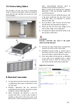
Page 22: ... it from the electricity supply with one of these devices The earth wire must be sufficiently long so that if the strain relief fails the live wires of the connecting cable are subjected to tension before the earth wire Any superfluous cable must be removed from the installation area beneath the appliance Make sure that the local mains voltage is the same as the voltage on the rating label Full pr...

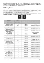
Page 23: ...T3 1 HEATSINK TEMPERATURE T4 1 No power is delivered to the zone Off or H c On Power Hot glass over a zone residual heat COIL TEMPERATURE T5 1 COIL TEMPERATURE T6 1 Off H 1 For T1 T2 T3 T4 T5 and T6 values see the corresponding drawing 2 Due to some kinds of overvoltage disturbances in the mains that can damage internal electronic the ECOOK system includes an overvoltage protection circuit to prot...

Page 24: ...App off When the fault disappears User interface temperature sensor short circuit FE App off When the fault disappears User interface temperature sensor open circuit Ft App off When the fault disappears User interface overtemperature Fc App off When user interface temperature T EEPROM fault FH App off Microcontroller A D converter multiplexer fault FJ App off When the fault disappears Ambient Ligh...

Page 25: ...ig 30 Fig 30 Do not use jets of steam for cleaning To remedy any anomalies of functioning please contact qualified personnel PERIODICALLY The hob and extractor area below can be cleaned with water and neutral liquid detergent Don t use solvents or abrasives To wash the interior part just lift the hob by placing your hands in the suction holes and pull upwards The hood will remain open to carry out...

Page 26: ...5 Noise db 48 67 Motor Power W 167 Hob Power kW 7 2 Voltage V 220 240 Outlet Width mm 150 Energy Class A COIL Ø MINIMUM PAN Ø 145mm 90mm 210mm 130mm Power Level Coil 210 Coil 145 Bridge Booster P 2000W 1600W 9 1500W 1200W 2400W 8 1300W 1000W 2000W 7 1100W 800W 1600W 6 900W 600W 1200W 5 700W 500W 1000W 4 500W 400W 800W 3 300W 300W 600W 2 200W 150W 300W 1 100W 75W 15W ...

Page 27: ...d Sound Power Emission at minimum speed dB A 48 A weighted Sound Power Emission at maximum speed dB A 65 A weighted Sound Power Emission at intensive or boost speed dB A 67 Power consumption off mode PO W 0 5 Power consumption in standby mode PS W 0 5 Time increase factor 0 9 Energy Efficiency Index EEI 51 2 Measured air flow rate at best efficiency point QBEP m3 h 420 Measured air pressure rate a...

Page 28: ...28 13 Dimensions 8 TIMER 510mm 830mm BOOSTER 0 0 0 0 800mm 830mm 385mm 145mm 215mm 86mm 20mm 15mm BACK 128mm 244mm 116mm 5mm 485mm 510mm 380mm SIDE 128mm 244mm 116mm 5mm ...

Page 29: ...29 ...

Page 30: ...30 ...

Page 31: ...31 ...

Page 32: ...y West Yorkshire LS27 7JZ CD UK Ltd T A Air Uno is a company registered in England and Wales Registration No 2905619 of of this vested part not be reproduced The of this are accurate at the date of but because has a of may be and be or are The rights of the customer are not affected ...

Reviews: