31
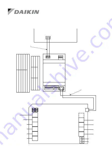
(657212) Wiring Diagram
Wiring Diagrams contd.
RS4
85
A+
B-
Hom
eKi
t
S/A
2
E/
M
T
Z1
Z2
Z3
Z4
Z8
Z7
Z
6
Z
5
B2
B
1
L
N
RS485
A+ B-
S3
S4
S1
S/
A
1-
2:
S
uppl
y
Air
Sen
so
rs
E/
M:
E
xte
ns
io
n M
od
ule
T:
To
uch
scr
een
Z1
...Z8:
Z
on
e
D
am
pe
rs
L
and N:
24V
AC Power
Supply
RS485:
AC Gateway
AC
G
at
ew
ay
P1 P2
P1 P2
AirTouch
2 Plus
S/A
1
657
211
(R
S485
C
ab
le
) f
ro
m
P
oly
air
e
(P
ro
vid
ed
wi
th
th
e g
ate
wa
y)
M
as
te
r/Sla
ve
S
ettin
g
S1
S4
G
at
ew
ay
A
s
0111
00
00
Sl
av
e
1111
00
00
M
as
te
r
Tw
o C
ore
ca
bl
e,
str
ipped
w
ires
fiel
d
pr
epa
red
AC
Ind
oo
r
PC
B
G
ate
wa
y A
dd
re
ss
S
etting
S3
G
atew
ay
A
ddr
es
s
10
000
001
1
01
000
001
2
11
000
001
3
00
100
001
4
657
21
2
N
ot
e:
0-
O
ff,
1
-O
n
1
3
2
4
E/
M
T
Z1
Z
2
Z3
Z
4
Z
8
Z7
Z6
Z
5
R
S4
85
G
ate
w
ay
N
L
24
V
AC
B
A
E/
M
: T
o E
xte
ns
io
n M
od
ule
T:
T
o T
ou
ch
sc
re
en
(C
on
so
le
)
Z1
-Z
8:
T
o Z
on
e P
or
ts
1
-4
: S
up
ply
A
ir S
en
so
rs
R
S 4
85
: T
o A
C G
ate
w
ay
s
2
4 V
A
C
: T
o P
ow
er
Su
pp
ly
To
Damper
Motors
To
Damper
Motors
AirTouch
2+
To
Transformer
To
Ext
ension
Module
To
Touc
h
Screen
(O
ptional
)
RS4
85
A+
B-
Hom
eKi
t
S/A
2
E/
M
T
Z1
Z2
Z3
Z4
Z8
Z7
Z
6
Z
5
B2
B
1
L
N
RS485
A+ B-
S3
S4
S1
S/
A
1-
2:
S
uppl
y
Air
Sen
so
rs
E/
M:
E
xte
ns
io
n M
od
ule
T:
To
uch
scr
een
Z1
...Z8:
Z
on
e
D
am
pe
rs
L
and N:
24V
AC Power
Supply
RS485:
AC Gateway
AC
G
at
ew
ay
P1 P2
P1 P2
AirTouch
2 Plus
S/A
1
657
211
(R
S485
C
ab
le
) f
ro
m
P
oly
air
e
(P
ro
vid
ed
wi
th
th
e g
ate
wa
y)
M
as
te
r/Sla
ve
S
ettin
g
S1
S4
G
at
ew
ay
A
s
0111
00
00
Sl
av
e
1111
00
00
M
as
te
r
Tw
o C
ore
ca
bl
e,
str
ipped
w
ires
fiel
d
pr
epa
red
AC
Ind
oo
r
PC
B
G
ate
wa
y A
dd
re
ss
S
etting
S3
G
atew
ay
A
ddr
es
s
10
000
001
1
01
000
001
2
11
000
001
3
00
100
001
4
657
21
2
N
ot
e:
0-
O
ff,
1
-O
n
Summary of Contents for AirTouch 2
Page 1: ...airtouch net au Installer Manual...
Page 4: ...4 Compatible Brands Compatible Brands...
Page 19: ...19 Zone Setting...
Page 67: ...67...


