


6
IO-123114 Effective 12-04-2014
Be aware of the Teflon O-ring. Be sure to
replace the O-ring to attain a proper
seal. (The Teflon O-ring is located between
the two halves of the flowrator)
CAUTION
!
Pay close attention to the piston orienta-
tion. The pointed end of the piston MUST
go into the distributor body, towards the
coil. Failure to ensure this orientation will cause the piston
to be bypassed during operation which might damage the
outdoor unit.
CAUTION
!
II-6.
Replace the piston with one
of the correct size. Do not force
the new piston into the body.
Make sure the piston moves
freely in body.
II-7.
Assemble the two halves correctly and ensure that the white
Teflon O-ring is present between the two halves (See I-5). Slide the
13/16” nut onto the distributor body.
II-8.
Tighten the nut to a torque of approximately 10-30 ft-lbs.
Do NOT
overtighten the nut. Overtightening will impede the piston movement
during operation.
II-9.
If present, slide the rubber grommet back to position to prevent
air leakage.
8B. TXV Coils
Ensure that the TXV selected is compat-
ible with the refrigerant used in the out-
door system (R22 or R410A). TXV caps are
painted green for R22 or pink for R410A. In absence of col-
or, the caps will be marked with the compatible refrigerant.
CAUTION
!
The sensing bulb and TXV body MUST be
protected from overheating during braz-
ing. The sensing bulb and TXV body must
be covered using a quench cloth or wet cloth when brazing.
Pointing the brazing flame away from the valve and sensing
bulb provide partial protection only.
!
WARNING
Fig 8B-1. Components of a typical TXV assembly
The valves should be sized according to
the capacity of the outdoor unit. Failure to
install the right valve can lead to poor per-
formance and possible compressor damage.
CAUTION
!
Ensure that the TXV bulb is in direct con-
tact with the suction/vapor line. Gap be-
tween the bulb and tube should be avoid-
ed. Failure to do so will impair the proper functioning of the
TXV valve.
CAUTION
!
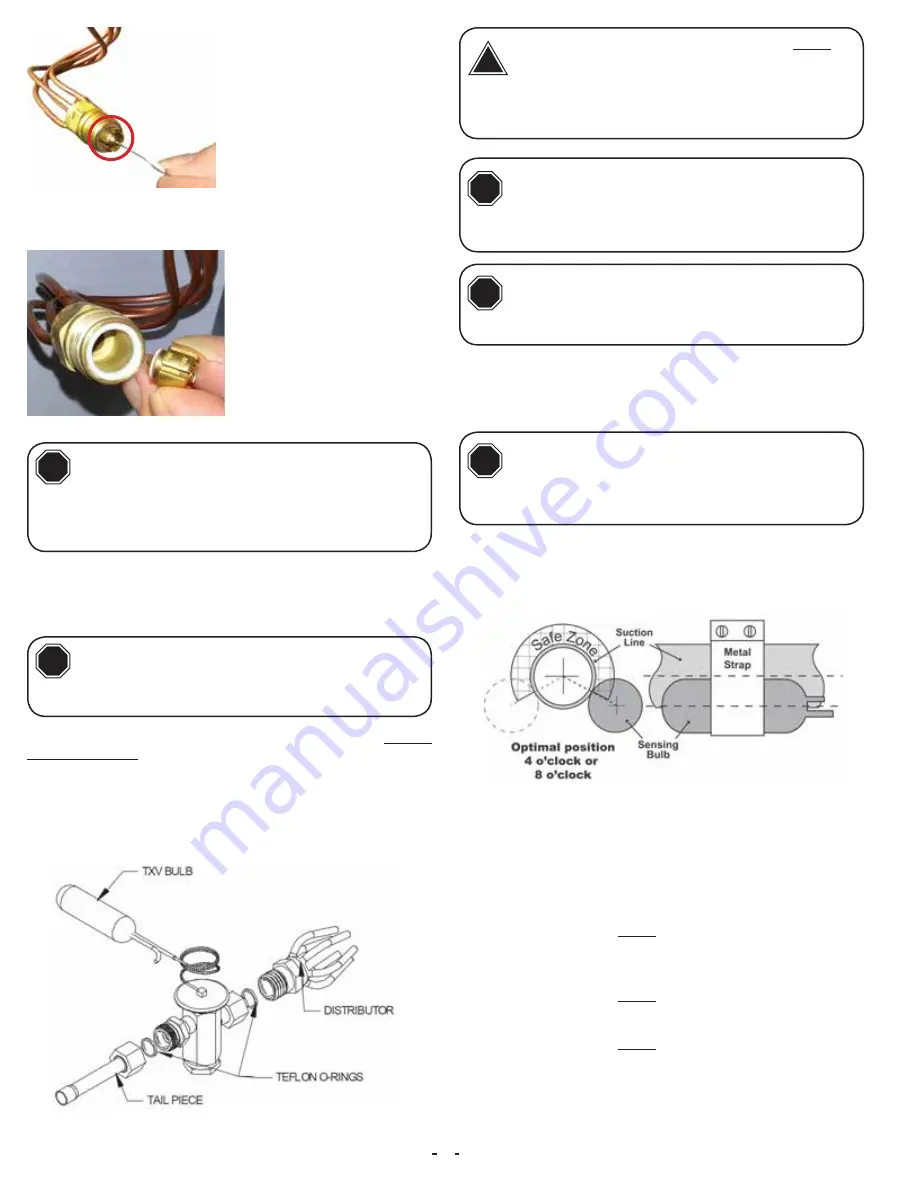
I. TXV Bulb Horizontal Mounting
The orientation and location of the TXV bulb has a major influence
on the system performance.
It is recommended that the TXV bulb be installed parallel to the
ground (on a horizontal plane). The bulb position should be above
and between 4 o’clock and 8 o’clock. Fig. 8B-2 shows the recom-
mended position for the TXV bulb installation in the horizontal plane.
The TXV sensing bulb SHOULD be mounted on the suction line ap
-
proximately 6” from the TXV or coil housing using the metal clamp
provided. In order to obtain a good temperature reading and correct
superheat control, the TXV sensing bulb must conform to ALL of the
following criteria:
1. The sensing bulb
MUST
be in direct and continuous
contact with the suction line.
2. The sensing bulb should be mounted horizontally on
the suction line.
3. The sensing bulb
MUST
be mounted above and between
the 4 and 8 o’clock position on the circumference of the
suction line.
4. The sensing bulb
MUST
be insulated from outside air.
A properly mounted sensing bulb will prevent false readings caused
by liquid refrigerant that may have formed inside the suction/vapor
line. Insulation will protect the sensing bulb from false readings due
to contact with warm air.
Fig 8B-2. Recommended location for horizontal TXV bulb mount
II-5.
Pull the piston out using a
small wire or pick. Verify the pis
-
ton size (size is typically stamped
on the body of the piston - Fig
8A-2). If a different piston size
is required by the outdoor unit
manufacturer, replace the piston
using the small wire provided with
the piston kit.


