PCBRM100 User’s Guide
Chapter 6: Maintenance
4101.00.902
6-18
To access the Flow Adjustment Screen:
1. Log on as “DRS27” or any “high level” security operator and select the Thumbs Up icon.
2. Using right side mouse button, click the Air-Vac logo. You are now in the ‘Hidden’ Setup window.
3. Select Setup from the menu bar.
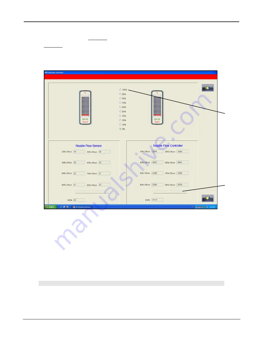
4. Select Adjustments/Nozzle Flow. The Nozzle Flow Adjustment screen will appear as shown below.
Making Flow Controller Verifications and Adjustments:
5. Click on the 100% radio button (A) on the Flow Adjustment Screen. The airflow will activate after 1-4
seconds.
6. Wait 45 seconds before making any adjustments.
7. Check the 100% scribe line on the flow meter. If the flow meter reads too high or too low, adjust-
ments can be made immediately by dragging or clicking on the track bar within the Nozzle Flow Con-
troller group box (B). The airflow should not be interrupted. The adjustments will be automatically ap-
plied and stable within 3-5 seconds. The track bar is always connected to the active flow rate
helping to minimize incorrect adjustments.
Note:
N
O ADJUSTMENT IS NECESSARY IF THE FLOW IS OFF BY LESS THAN THE THICKNESS OF THE
FLOAT
+/-. R
EAD THE BOTTOM OF FLOAT HEAD
(
LARGEST DIAMETER
).
(B)
(A)
Summary of Contents for PCBRM100
Page 1: ...PCBRM100...
Page 2: ......
Page 4: ...PCBRM100 User s Guide 4101 00 902...
Page 6: ...PCBRM100 User s Guide Chapter 1 Introduction Overview 4101 00 902 1 2...
Page 16: ...PCBRM100 User s Guide Chapter 1 Introduction Overview 4101 00 902 1 12...
Page 17: ...PCBRM100 User s Guide Chapter 1 Introduction Overview 4101 00 902 1 13 Left Side...
Page 18: ...PCBRM100 User s Guide Chapter 1 Introduction Overview 4101 00 902 1 14 Center Right Side...
Page 19: ...PCBRM100 User s Guide Chapter 1 Introduction Overview 4101 00 902 1 15 Rear...
Page 20: ...PCBRM100 User s Guide Chapter 1 Introduction Overview 4101 00 902 1 16...
Page 22: ...PCBRM100 User s Guide Chapter 1 Introduction Overview 4101 00 902 1 18...
Page 23: ...PCBRM100 User s Guide Chapter 1 Introduction Overview 4101 00 902 1 19 Left Side...
Page 24: ...PCBRM100 User s Guide Chapter 1 Introduction Overview 4101 00 902 1 20 Center...
Page 25: ...PCBRM100 User s Guide Chapter 1 Introduction Overview 4101 00 902 1 21...
Page 26: ...PCBRM100 User s Guide Chapter 1 Introduction Overview 4101 00 902 1 22 Laser Warnings...
Page 27: ...PCBRM100 User s Guide Chapter 1 Introduction Overview 4101 00 902 1 23 Front...
Page 28: ...PCBRM100 User s Guide Chapter 1 Introduction Overview 4101 00 902 1 24 Rear...
Page 30: ...PCBRM100 User s Guide Chapter 2 Facility Requirements 4101 00 902 2 2...
Page 32: ...PCBRM100 User s Guide Chapter 2 Facility Requirements 4101 00 902 2 4...
Page 33: ...PCBRM100 User s Guide Chapter 3 Start Up 4101 00 902 3 1 3 Start Up 3 Start Up 3...
Page 34: ...PCBRM100 User s Guide Chapter 3 Start Up 4101 00 902 3 2...
Page 38: ...PCBRM100 User s Guide Chapter 3 Start Up 4101 00 902 3 6...
Page 40: ...PCBRM100 User s Guide Chapter 4 Software Overview 4101 00 902 4 2...
Page 90: ...PCBRM100 User s Guide Chapter 4 Software Overview 4101 00 902 4 52 Adjustments...
Page 96: ...PCBRM100 User s Guide Chapter 4 Software Overview 4101 00 902 4 58...
Page 118: ...PCBRM100 User s Guide Chapter 4 Software Overview 4101 00 902 4 80...
Page 120: ...PCBRM100 User s Guide Chapter 5 Process Development 4101 00 902 5 2...
Page 158: ...PCBRM100 User s Guide Chapter 6 Maintenance 4101 00 902 6 2...
Page 180: ...PCBRM100 User s Guide Chapter 6 Maintenance 4101 00 902 6 24...
Page 182: ...PCBRM100 User s Guide Chapter 7 Error Messages 4101 00 902 7 2...


