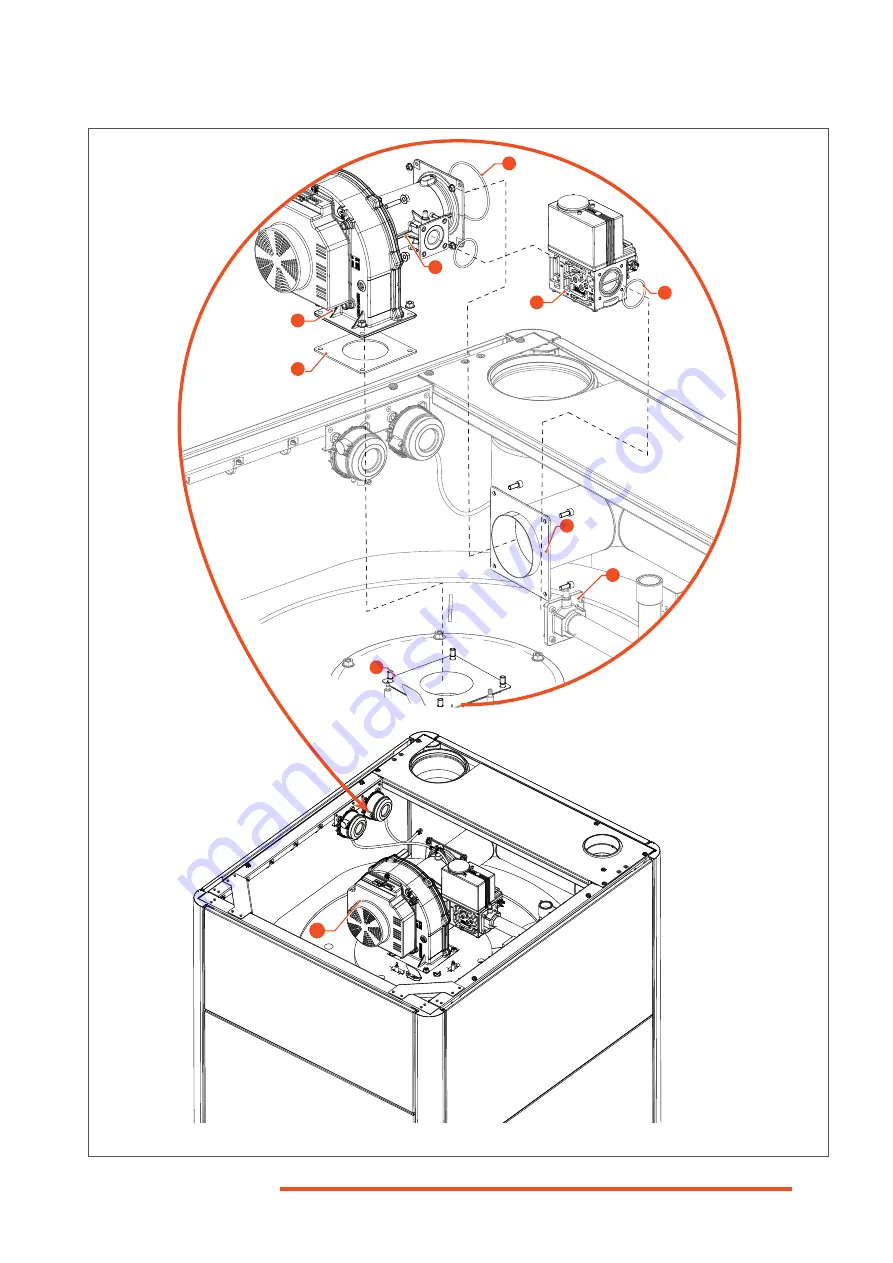
Fig. 30. TEXAS 230 - Removing and Installing the Fan/venturi/Gas Valve Assembly
3
2
6
9
4
5
1
7
8
10
I-71
H-093630_EN • 00
M
aintenance
Page 1: ...EN installation and maintenance manual FOR THE INSTALLER AND THE USER 99 230 kW FLOOR STANDING CONDENSING STORAGE WATER HEATER H 093630 00 TEXAS...
Page 2: ...S and Air APS Pressure Switches operation I 63 Removing Cleaning and Installing the Condensate Trap I 64 Removing and Installing the Ignition and Ionisation Electrodes I 66 Removing and Installing the...
Page 3: ...ith Any relevant explanation about the op eration of the appliance and the heat ing system as well as the safety devices that are provided Any instruction regarding periodic checks to be performed and...
Page 4: ...rted stopped using the ON OFF switch installed on the appliance ON OFF The electrical supply to the appli ance must be activated deactivated through the external circuit breaker or the power supply ca...
Page 5: ...kW P kW EXAMPLE G 5 H 093630_EN 00 General Information Appliance Marking The data plate is located at the back of the appli ance Appliance Naming In the documentation products of the Texas floor stan...
Page 6: ...appliance and its components is strictly forbid den without the prior written consent of the manufacturer If components need to be replaced only genuine factory parts or compo nents approved by the ma...
Page 7: ...nance manual A gas conversion sticker A set of components to be installed before commissioning A condensate trap and protective cover An air inlet silencer for B type chimney con nection and hardware...
Page 8: ...tection The pump and the burner are started as required when the water temperature drops below 5 C as measured by the appliance internal sensor installed on the return circuit The pump and or burner w...
Page 9: ...3 TEXAS 99 230 Components Front views KEY 1 Flue gas exhaust connexion 2 Combustion air inlet connection 3 Gas connection 4 On Off switch 5 Control panel access door 6 Control panel 7 Water tank insul...
Page 10: ...onisation electrode 19 Air pressure switch 20 Flue pressure switch 21 Gas pipe 22 Ignition transformer 23 Gas valve 24 Venturi 25 DHW tank with built in heat exchanger 26 Condensate dish with flue gas...
Page 11: ...trode 19 Air pressure switch 20 Flue pressure switch 21 Ignition transformer 22 Gas valve TEXAS 230 with built in gas pressure switch 23 DHW tank with built in heat exchanger 24 Condensate dish with f...
Page 12: ...to scroll through the menus icons functions or increase decrease a value af ter selecting a function KEY When entering a menu sub menu the slow rotation of the selector to the right clockwise allows t...
Page 13: ...list and to access the commissioning wizard Symbols appearing in the horizontal status bar Alarm Indicates an error in the system Maintenance Special operations It indi cates the presence of a mainten...
Page 14: ...r Heater TX 99 FS TX 230 FS dry weight kg 415 425 full of water kg 915 925 connections inlet outlet M in BSPP 2 recirculation M in BSPP 1 drain valve in BSPP 2 gas M in G 3 4 G 1 condensate drain mm 2...
Page 15: ...00 Technical Specifications Fig 8 Single Appliance Clearances View from the Top Clearances Min Recommended top mm 400 800 back mm 500 800 front mm 740 Front door fully open on hinges 1000 sides mm 10...
Page 16: ...ating energy efficiency wh 93 8 92 6 mixed water at 40 C V40 l 631 0 daily electricity consumption Qelec kWh 0 136 0 379 annual electricity consumption AEC kWh 30 0 83 0 daily fuel consumption Qfuel k...
Page 17: ...Pa 200 CO emissions G20 mg kWh 4 30 9 67 G25 6 44 10 74 G31 10 74 20 41 CO2 contents G20 0 3 8 2 9 2 8 2 9 2 CO2 contents G25 0 3 8 3 9 1 8 2 9 1 CO2 contents G31 0 3 10 5 11 0 10 5 11 1 O2 contents G...
Page 18: ...31 AT CZ FI RO CH CZ ES GB GR HR IE IT LT PT SI SK TR AT CH CZ ES GB SK II2L3P G25 G31 FR RO II2E 3P G20 G31 BE FR II2E R 3P G20 G31 BE II2Esi3P G20 G25 G31 FR II2Er3P G20 G25 G31 FR Gas Data TX 99 FS...
Page 19: ...m Do not operate the appliance when the casing is open IF YOU SMELL GAS DO NOT Use an open flame Smoke Use electrical devices phones doorbells etc or switches DO Close the gas supply Open all doors an...
Page 20: ...vent the ingress and accu mulation of dust In case of abnormal noises in the sys tem or the appliance please notify a qualified professional Any setting of the appliance by the end user using the inst...
Page 21: ...he Information icon for details on the error and maintenance code Maintenance icon Starting the Appliance The first start up of the appliance after its installation must be performed by a qualified pr...
Page 22: ...ure C This value indicates the current temperature as detected by the system sensors Nominal setpoint C DHW temp setting Operating mode Off On When Off Hot water heat ing is switched off when On Hot w...
Page 23: ...Time 01 00 Date 01 01 2030 Regional settings 2 3 Start of summertime 25 03 End of summertime 25 10 Regional settings 3 3 Language English Deutsch Fran ais Italiano Nederlands Es pa ol Portuguese Dans...
Page 24: ...age Selection English Language Regional settings 3 3 Symbols used for the operation of the selector turn the selector to the left or to the right depress shortly the rotary se lector turn the selector...
Page 25: ...et time program 06 00 to 22 00 08 00 to 18 00 Add phase Start 06 00 End 22 00 06 12 00 18 24 06 12 00 18 24 06 12 00 18 24 06 12 00 18 24 06 12 00 18 24 Start 02 00 06 12 00 18 24 4 Time Program Defin...
Page 26: ...hrough the external power cutting device fuse circuit breaker etc All connections electrical flue pipe hydraulic gas must be carried out in accordance with current standards and regulations in force I...
Page 27: ...ing components or rest the appliance on protruding components Failure to comply with these recom mendations can result in damage to the appliance or injuries to the personnel Using a forklift truck or...
Page 28: ...ncer 1 into the air inlet con nection and fasten with provided screw i OFF 1 2 The air silencer 1 must be installed if the selected chimney connection is the B type open In case of C Type chimney conn...
Page 29: ...ing Side of the Front Door on page I 30 1 Holding the top right hand side of the door disengage the upper stud from its receptacle 2 Repeat the operation with the bottom right hand side to disengage t...
Page 30: ...side of the frame releasetwoscrewsfromtop bottomhinges 3 Remove and retain for reinstallation rotate each hinge 3 180 and reinstall with two retained screws 5 Lift the front door 1 off the left side...
Page 31: ...diameter of discharge pipe D1 should be not less than the nominal outlet size of the tem perature relief valve 3 52 Where a manifold is used it should be sized to accept and discharge the total disch...
Page 32: ...es should be connected to the pipe Plastic pipes should be joined and assembled with fittings appropri ate to the circumstances in which they are used as set out in BS EN ISO 1043 1 Where pipes cannot...
Page 33: ...ge pipe arrangement Table G3 Sizing of copper discharge pipe D2 for common temperature relief valve outlet sizes Example of discharge pipe sizing Figure on previous page shows a G1 2 tempera ture reli...
Page 34: ...and usage Safety Instructions for the DHW Circuit Flush thoroughly the circuit be fore operation It is recommended to install a filter 100 m to prevent res idues to contaminate the cir cuit Setting th...
Page 35: ...5 H 093630_EN 00 Product Installation Typical Hydraulic Connections DHW Circuit Isolating valve Filling valve Draining valve Check valve Three way mixing valve Pressure reducer Expansion vessel Safety...
Page 36: ...arly Make sure to secure the flue piping to a solid structure Exclusively use the provid ed brackets to support the flue system When assembling the pipes make sure not to put any stress on the com pon...
Page 37: ...m pow er might decrease For B and C type appliances the flue gas exhaust pipes must at least comply with the category T120 H1 W1 2 O30 LI E U when using parallel piping and T120 H1 W1 2 O00 LI LE E U0...
Page 38: ...the boiler room Remark Can be used for cascading B23 Make sure that the ventilation openings remain unobstructed at all times Combustion circuit Open Flue Discharged to the outside through positive pr...
Page 39: ...combustion air inlet and flue gas outlet including wind pressures is indicated in the technical specifications maximum allowable temperature of combustion air is 40 C Condensate flow is allowed into...
Page 40: ...ough separate terminals that may termi nate in zones of different pressures Additional requirement Orifices may NOT terminate on opposite walls of the building C53 C43 Combustion circuit Sealed Connec...
Page 41: ...r AIC representa tive for more information Engineering the Chimney System The flue system length must be calculatedsoastoensureasafe performance of the system Make sure to install the appliance with t...
Page 42: ...ssure regulator if required Do not exceed the maximum gas pressure The conversion of the appliance from natural gas to G31 liquefied petroleum gas propane or the re verse can only be performed by a qu...
Page 43: ...justed in factory for G20 natural gas to op erate with G25 natural gas or G31 propane gas Gas conversion to this appliance does not require component replacement only adjustments of gas valve through...
Page 44: ...ex head size 4 Screwdriver Torx T15 TEXAS 230 Procedure 1 Remove the inspection cover OR the top panel to get access to the gas valve Refer to Opening and Closing the Front Door and Access Panels on p...
Page 45: ...Refer to Table 1 Table 2 on page I 43 5 Rotating the selector 1 adjust the ignition fan speed according to the values in Table 1 Table 2 on page I 43 6 Press the selector 1 to confirm and save the va...
Page 46: ...operations 1 3 Set Chimney sweep function to On Set Burner output to Full load 4 Check the CO2 or O2 contents displayed on the gas analyser and compare the values with those in the table below 5 If th...
Page 47: ...t the setting menu i 10 Restart the appliance to check the ignition be haviour Control the correct operation of the appliance by repeating steps 1 to 7 11 Reseal the offset screw 3 using some paint or...
Page 48: ...ing diagram If high voltage cables are installed on a low voltageterminal theelec tronic board will be damaged When connecting wires to the termi nals check that the connection is se cure and that all...
Page 49: ...e sure that the power supply to the appliance is deactivated pow er supply cable disconnected from the appliance before accessing the high voltage terminal strip 2 Remove one screw 1 from the top of t...
Page 50: ...RD RD RD BK BK BK RD GNYE GNYE GNYE GNYE GNYE GNYE GNYE BN BU BU BN BN BU BN BU BU BN GNYE BU BU BU BU BN BN BN BN BN 7L4 5L3 3L2 1L1 8T4 6T3 4T2 2T1 BN BU BU BN BU BU BU BN BN GNYE B N BU GNYE GNYE G...
Page 51: ...ignal GND H1 H4 H5 X6a X10a 9 L N C4 L1 K9 W3 I5 U1 J1 DS1 X50 WH WH WH WH RD RD RD RD RD RD BK GY BN GY GNYE BN BU WH BK WH PWM HALL GND BN GY BK WH 24V 1 2 3 2 1 RD WH GNYE BU BN BK RD Red Black Gre...
Page 52: ...BN BU BN BU BU BN GNYE BU BU BU BU BN BN BN BN BN 7L4 5L3 3L2 1L1 8T4 6T3 4T2 2T1 BN BU BU BN BU BU BU BN BN GNYE B N BU GNYE GNYE GNYE GNYE GNYE T1A GNYE GNYE Front Grounding Strip P5 GNYE 1 2 PE N...
Page 53: ...3 I5 U1 J1 DS1 X50 WH WH WH WH RD RD RD RD RD RD BK GY BN GY GNYE BN BU WH BK WH PWM HALL GND BN GY BK WH 24V 1 2 3 2 1 RD WH GNYE BU BN BK RD Red Black Green Yellow Blue Bronze GY Grey WH White WH I2...
Page 54: ...ure that the condensate trap is full of water before starting up the appliance Conditions Procedure 1 Connect the water network to the DHW inlet circuit 2 Make sure that the draining valve if in stall...
Page 55: ...tion adjustments Refer to the procedure on the right i Combustion Adjustment Conditions ON Tools and material Flue gas analyser Wrench hex head size 4 Screwdriver Torx T15 TEXAS 230 Procedure 1 Remove...
Page 56: ...rt End user Symbols used for the operation of the selector turn the selector to the left or to the right depress shortly the rotary selector turn the selector to adjust the value then depress the sele...
Page 57: ...tional information i Test wiring This section allows to check that the signals to and from the equipment main board are correct No test is the standard configuration Change it if you want to perform w...
Page 58: ...kday 1645 Legionella function setpoint 65 C 1641 Legionella function periodically 3 1642 Legionella function weekday Monday Tuesday Wednesday Sunday Skip Skip Redo Redo Continue Continue System setup...
Page 59: ...Yes 7170 Telephone customer service 0 Commissioning wizard 7167 Commissioning wizard Off On next time the control device is switched on Redo Complete parameter list Commissioning wizard Select this f...
Page 60: ...s are tight and se cured Before performing any main tenance operation shut down the appliance using the ap pliance on off switch and isolate the electrical supply of the appliance through the external...
Page 61: ...r leaks both inside and outside the appliance water gas flue and condensate X X Clean any filter dirt separator present in the hydraulic circuit as required Refer to manufacturer s documentation X X C...
Page 62: ...e control panel When in the OFF position the switch internal light goes out 2 To completely cut the power supply to the appliance either disconnect the power sup ply cable from the appliance or use th...
Page 63: ...ing the Air Pressure Switch and Flue Pressure Switch 4 FPS 4 blow air into the hose while it is con nected to the flue pressure switch and to the measuring device 5 APS 3 suck air from the hose while...
Page 64: ...2 Release two screws 9 and open the con densate trap cover 10 Retain cover and hardware for reinstallation 3 Remove the cover gasket 11 Discard OFF i 4 Wipe clean the condensate level switch 12 attach...
Page 65: ...I 65 H 093630_EN 00 Maintenance Fig 27 Cleaning the Condensate Pipe and Trap 1 2 3 4 5 6 7 8 9 9 10 11 12...
Page 66: ...3 Release two screws 1 from the electrode flange 4 Remove the electrode and screws 1 from the fan plate 3 Discard as required 5 Remove electrode gasket 2 and discard as required Installation procedur...
Page 67: ...Fig 28 Removing and Installing the Electrodes 3 I 67 H 093630_EN 00 Maintenance 1 2 3 4 5 mm 0 5 0 5...
Page 68: ...quired OFF i 13 Remove the electrodes as required refer to Removing and Installing the Ignition and Ionisation Electrodes on page I 66 14 Remove the burner as required refer to Re moving and Installin...
Page 69: ...Fig 29 TEXAS 99 Removing and Installing the Fan Venturi Assembly and Gas Valve 3 4 7 5 2 1 6 9 8 10 I 69 H 093630_EN 00 Maintenance...
Page 70: ...an assembly 1 and fan gasket 2 and retain with hardware for reinstallation Discard fan gasket 2 10 Remove the electrodes as required refer to Removing and Installing the Ignition and Ionisation Electr...
Page 71: ...Fig 30 TEXAS 230 Removing and Installing the Fan venturi Gas Valve Assembly 3 2 6 9 4 5 1 7 8 10 I 71 H 093630_EN 00 Maintenance...
Page 72: ...ition of the burner tube 2 Clean with compressed air to remove residues If it is in bad condition after cleaning replace it 3 Remove the burner plate Refer to Remov ing and Installing the Burner Plate...
Page 73: ...Fig 31 Removing and Installing the Burner 1 2 3 4 5 6 7 8 I 73 H 093630_EN 00 Maintenance TEXAS 99 TEXAS 230...
Page 74: ...racked and dam aged or the burner plate 2 shows discolouration or burns 4 Remove it as required by releasing three nuts and washers 4 Retain hardware for reinstal lation 5 Discard the damaged insulati...
Page 75: ...Fig 32 Removing the Burner Plate 1 4 2 3 I 75 H 093630_EN 00 Maintenance...
Page 76: ...check the condition of the combustion chamber If it is dirty clean it Cleaning Procedure 1 Using a nylon bristle brush sweep the walls of the combustion chamber OFF 2 Using an industrial vacuum cleane...
Page 77: ...open the inspection hole 1 and inspect the bottom of the tank with a torch Close it after inspection OFF 3 If required flush away the residues with wa ter as follows open the cold water filling valve...
Page 78: ...es To access the Commissioning and the Engineer levels proceed as follows Menus and Settings The table on the following page contains some of the menus and submenus for the installer The last column a...
Page 79: ...gnment device 1 Zone 1 Zone 1 and 2 Zone 1 and 3 All zones All zones 48 Warmer cooler device 1 None For zone 1 only For all assigned zones 70 Software version Time Program 4 DHW Set time program Refer...
Page 80: ...pages 7130 Chimney sweep function Off On Off 7131 Burner output Partial load Full load Max heating load Max heating load 7140 Manual control Off On Off 7167 Commissioning Wizard Off On On Diagnostics...
Page 81: ...ral times inform AIC technical support 111 Temperature limiter safety shutdown Contact AIC technical support 126 DHW charging temperature not reached Check operation and heat up times for DHW 127 DHW...
Page 82: ...appliance model can apply to the following air pressure switch flue pressure switch condensate level switch burner plate temp limit switch Additional external max temp limit switch Additional external...
Page 83: ...ror Correct device address 352 Pressureless header ad dress error Correct device address 353 Sensor B10 missing Common flow sensor missing Check parameters connection and component 378 Internal repeti...
Page 84: ...ss of connections and circuit 2 Check that pressure measuring points are closed Unburned gas smell Leak in flue gas circuit 1 Check tightness of connections 2 Check there are no obstructions in the fl...
Page 85: ...erature too high compared to setpoint Appliance controller malfunction 1 Check temperature setpoint 2 Check controller operation 3 Check position of temperature sensors Heat exchanger reaches temperat...
Page 86: ...ting circuits Floor heating Radiators Other Cascade Y N Number of boilers Water Water hardness at start up mol m or mg l System volume L Additive s Antifreeze Y N Type Quantity Gas Type Heating value...
Page 87: ...gas Open or closed system Dimensions of combustion air open ings if closed system cm2 Material of flue piping Diameter and length of piping sys tem mm m Chimney system engineered by Calculated pressu...
Page 88: ...controller Other controller Y N Type Optional modules installed Y N Type Optional items installed Y N Outdoor sensor Y N Type Room unit s Y N Type Others Miscellaneous The end user has received all re...
Page 89: ...I 89 H 093630_EN 00 Additional Information for the Installer Combustion Parameters Log Sheet CO2 Flue gas T Remarks Name Date Signature...
Page 90: ...I 90 H 093630_EN 00 Additional Information for the Installer Water Parameters Log Sheet Water Filling Date Water Top up Date Water Quality Water Treatment Remarks Name signature...
Page 91: ...I 91 H 093630_EN 00 Declaration of Conformity...
Page 92: ...www myaic eu AIC Europe B V Graafschap Hornelaan 163A NL 6001 AC Weert The Netherlands...