background image

Presto Detacher


©  2012  AIC WAIKATO LLC 

608-526-6882


65 

(Used to operated a vacuum cylinder) 

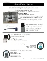
20456 - 24VDC 320 High Capacity Valve (no fittings) 

Fittings Options: 

80604 - IN 1/4” x 3” Galv Nipple 
80603 - OUT 1/4" PT x 3/8" Nylon Tube 90° 

20478 - 24VDC 3-Way Shifting Mac Valve Series 35 w/o Fittings 

Fittings Options: 

80600 - 1/8” PT x 5/32” PTC  

80602 - 1/8” PT x 1/4” PTC 

Fittings Options: 

80600 - 1/8” PT x 5/32” PTC 
80602 - 1/8” PT x 1/4” PTC 
80609 - 1/8" PT x 1/4" PTC 90° 

20463 - 24VDC Air 4-Way Mac Valve w/o Fittings 5.4 Watts 

72133 Two STALL VACUUM ONLY OR 72134 Two STALL AIR ONLY 

(4 - 24 VDC Valves, Fittings, Box w/2" bungs, wire strain reliefs)  

72135 Two STALL AIR AND VACUUM 

(2 Air & 2 Vacuum-Valves, Fittings, Box w/2" bungs, wire strain reliefs)  

20133 - 24VDC M193 Valve w/o fittings 
Fitting Option: 

80605 - 1/4”PT x 3/16” Nylon Tube 90° 
80603 - 1/4”PT x 3/8” Nylon Tube 90°  
80606 - 1/4”PT x 5/32” PTC 90° 
80607 - 1/4”PT x 1/4” PTC 90° 


Components Include: 

1.  Sealed Plastic Enclosure 10 x 8 x 6 
2.  72138 - Air or Vacuum only Valve set w/ fittings (pictured)   
       72137 - Air and Vacuum valve set w/ fittings (1set) (not 

pictures) 
3.    2” Strain Reliefs for Wires Entering from the Detachers 

22464 - DIN type connector 

with 25" leads for M193 

Spare Parts - Valves 

Summary of Contents for Presto Detacher 70100

Page 1: ...Presto Detacher 2012 AIC WAIKATO LLC 608 526 6882...

Page 2: ...ings Set Up Table 26 Definitions 31 Stall Addressing 36 Network Termination 39 Presto Switch Operation 40 Presto Light Operation 41 Changing from Milk to Wash and Wash Mode 42 Review Data 43 Control E...

Page 3: ...ion of the products listed herein and does not express or imply a warranty that the products will necessarily conform to the illustrations or descriptions presented herein AGRICULTURAL INSTRUMENTS COR...

Page 4: ...These products will damage the plastic Certain materials contain ingredients that will attack plastic parts Do not expose the plastic parts to the following but not limited to Iodine teat dips Fly Sp...

Page 5: ...r more power supplies are used in the same installation the negative outputs must be tied together by adding an 14 gauge jumper wire tying the negative DC outputs together of each power supply This es...

Page 6: ...ttach Detach Right Auto Manual Left Four Line Backlit LCD Display Presto Detacher Control Hanger or mounting brackets are included but not shown When the An alyst is installed in a parlor stainless st...

Page 7: ...wo specialized tools for Wire Jacket s a Jacket Cutter and Scotchlok Crimper Wire Splicers 1 Scotchlok 2 Wire Wizard Tools 1 Wire Jacket Cutter 2 Wire Loc Crimper NOTICE Electrical Good Wiring Practic...

Page 8: ...ue Silver 1 Connect 3 Wires 2 Completely Tape Silver Wire COMPUTER Last Unit Network Terminated on PCB Two Switches ON 485 Parlor Network 3 Wire 485 Network From Computer to first Detacher Control dai...

Page 9: ...9 VERY IMPORTANT Must use Di Electric Grease Splicing Power Wires Power Supply Power Wire Hook up Wire Wizard Brown 24 VDC Blue 24 VDC 1 Strip Wire Insulation 1 4 inch 2 Apply Di Electric Grease to e...

Page 10: ...AIC WAIKATO LLC 608 526 6882 10 Splicing Wires from Detacher Stall Control to Flow Cell Splicing Flow Cell Sensor Wires Splicing Flow Cell 4 Wire Cable Black White Green Red Splice by using Connect 4...

Page 11: ...3 W Cable 3 W Cable Silver BLUE WHITE 8 W Cable White Black MLSO Valve 4 W Cable 485 Network IN and OUT Two 3 Wire Cables Polarity not Important Red Green Cylinder Valve Yellow Orange Black Blue O N P...

Page 12: ...er BLUE WHITE 8 W Cable White Black MLSO Valve 4 W Cable 485 Network IN and OUT Two 3 Wire Cables Polarity not Important Red Green Cylinder Valve Yellow Orange Black Blue O N Power In Green Red Milk S...

Page 13: ...W Cable Silver BLUE WHITE 8 W Cable White Black to MLSO Valve Precision Valve Head 4 W Cable IN and OUT Two 3 Wire Cables Polarity not Important Red Green to Cyl inder Valve Orange Yellow to Quick St...

Page 14: ...al Interface Two network cables are used on larger systems greater than double 10 to speed up communications A single port system travels around the parlor and ends at the last stall Note the detacher...

Page 15: ...hutoff side of the valve and the red wire hooks to the vacuum cylinder side of the valve The gray shifting valve uses a positive ground NOTICE NOTICE WHT BLK RED GRN BLU BR To Flow Cell From 4 conduct...

Page 16: ...remote switching applications When used the remote switch provides the same functions as the right attach detach switch on the Presto control The following Puffer Switch is the remote switch option A...

Page 17: ...Unit Maintain at least a 6 inch rise in the milk hose prior to entering the flow cell milk inlet This assures consistent milk slugging action Flow Cell Milk Outlet Connect 5 8 or 3 4 milk hose from t...

Page 18: ...omponents typically mounted in the are the Presto Detacher Controls flow cells shift valves and cylinders The power supply normally is installed in the utility room and computer in the office The Pres...

Page 19: ...istent flow patterns at all the milking locations in the parlor There are two flow cell SS mounting brackets that can be used depending on the installation requirement In all cases it is important to...

Page 20: ...e 50111 Flow Cell Holder is used for both right and left hand mounting allowing it to be used on either side of the parlor To change to RH or LH milk entry the SS mounting bracket is flipped over with...

Page 21: ...and sensor mounting 3 The SS mounting plate can be welded bolted or banded to a solid mounting location 4 To assure consistent milk slugging all the SS mounting plates must be horizontally leveled and...

Page 22: ...MLSO floats in the milk hose however it is important that the MLSO be installed so it drains properly Therefore the milk flow should be as follows Milk Inlet from the claw Milk Outlet to the milk pip...

Page 23: ...helf by leveling and lag screwing the shelf to a wall or if using a desk or other setting location Set the power supply on the shelf or other desired location Mounting the Switcher Power Supplies The...

Page 24: ...pplies must have a dedicated power input meaning the 120 VAC outlet should come straight from the service entry breaker box with no other applications pulling power from the circuit 2 When powering a...

Page 25: ...Previous Power In Wire Nuts injected with dielectric gel Scotch lock or equiv alent RED GRN BLK WHT To Detacher To Cylinder Valve To ML Shut off 8 conductor cable 4 conductor flow cell cable From 8 c...

Page 26: ...ouch the or click on the cow screen and proceed to the desired Tracker Elite category The computer must be set up See Tracker Set up and Operating Manual Checking the communication network 1 Switch th...

Page 27: ...lk Yield Calibration Immediately after the system is started during the first milking it is important to determine the appropriate end of milking setting for the dairy Do so accordingly End of Milking...

Page 28: ...f Delay 0 to 60 seconds 1 second 8 seconds Increase to milk cows drier decrease to milk cows wetter Max Milking Time 0 to 20 minutes 30 seconds 0 seconds Unit will detach after the maximum time has ex...

Page 29: ...f less sensitive decrease to make more sensitive Kick Off Temp Drop 5 10 Degrees F 1 Degrees F 0 Decrease to make Kick off feature more sensitive Increase to make less sensitive Make Meters Read Highe...

Page 30: ...es reduces output voltage by after a full out put for 400 milliseconds Yes for ON No for OFF Number of Groups 1 to 26 1 4 Defines the number of groups lots of cows being milked Parlor Type Low Line Hi...

Page 31: ...t was powered down In Idle mode the Presto powers up in the detach mode and in wash the Presto will power up in the wash mode Pre V1 48 Yes No No The Presto control light blinking sequence changed at...

Page 32: ...ning 1 80 or greater can run as Advanced Communication Statistics This screen helps to diagnose networking communication errors with the stall control Exercise Outputs Cylinder Shutoff Cyl Off On Shut...

Page 33: ...y This setting controls the amount of foremilk that the unit will ignore at the beginning of milking before it monitors the conductivity Milk Letdown Delay The letdown delay occurs at each attach and...

Page 34: ...y will require a different setting due to variation in vacuum level hose lengths air admission and milk lift To properly calibrate note the complete milk weight provided the Using an accurate scale co...

Page 35: ...s the operator to select the temperature to indicate an alarm condition Standard milk temperature is 102 0 F 39 1 C Setting the alarm temperature above 102 5 F 39 2C is recommended under standard cond...

Page 36: ...102 0 F 39 1 C Setting the alarm temperature above 102 5 F 39 2C is recommended under standard conditions Remember to calibrate the milk temperature according to the Calibrate Milk Temperature Offset...

Page 37: ...per right hand of the Presto PCB Now the addressing can be done from the keypad To initiated entering the stall address with the keypad select No The next prompt will ask you how large the parlor is t...

Page 38: ...tor wire Addressing the Presto stall controls is neces sary for the network to work and it should be done in the se quence the operators will be milking the cows This is neces sary to facilitate the c...

Page 39: ...stalls are hooked to the Herd Tracker the first 32 stalls are addressed as bank A and the remaining stalls are addressed as bank B When 65 96 stalls are hooked to the Herd Tracker the first 32 stalls...

Page 40: ...1 OFF ON OFF ON ON 12 OFF ON ON OFF OFF 13 OFF ON ON OFF ON 14 OFF ON ON ON OFF 15 OFF ON ON ON ON 16 ON OFF OFF OFF OFF 17 ON OFF OFF OFF ON 18 ON OFF OFF ON OFF 19 ON OFF OFF ON ON 20 ON OFF ON OFF...

Page 41: ...lor The remainder of the units must be turned OFF Please see the following picture for the switch settings Network Termination Switches Both Switches are Up for ON and down for OFF The end stall shoul...

Page 42: ...omatic milking mode hold the switch in for 2 3 seconds until the group number on the screen changes to the desired group number This is only required on one stall since the subsequent attaches will au...

Page 43: ...ders and controls 1 Turn power supply on and enable the air supply and or vacuum supply to the detachers 2 Verify in the attached mode that the detacher extends the rope or chain and the shutoff valve...

Page 44: ...ne Seconds above wash solution threshold actual temperature Second Line The second line of the display provides an enable or disable function After switched to wash by pressing the left switch the ope...

Page 45: ...ing the first milking it is important to determine the appropriate end of milking setting for the dairy Do so accordingly End of Milking EOM The end of milking detach flow rate and delay setting deter...

Page 46: ...That is the first record in is added to the top of the data list and the last record is removed Cow Data Display The second data review display shows individual milking data information Also See Herd...

Page 47: ...s section at their specified intervals Unless otherwise noted procedures in this section are to be performed by the owner Carefully read and follow pertinent instructions and safety messages in this s...

Page 48: ...inse and wash routine refer to your wash instructions for details 4 Just before the next milking sanitize the milk contact surfaces according to your normal washer instructions 5 To end the wash mode...

Page 49: ...x screws holding the PC board in place remove the board 4 To mount the new circuit board follow the instructions in reverse order Snug tighten the control box screws over tightening can stress the con...

Page 50: ...holes in the Cow Simulator The Cow Simulator will fit as shown below Step Three Switch the Control into the milking mode Step Four If the milk yield circuitry is operating correctly the will count mil...

Page 51: ...set Decrease Conductivity OFFSET Detach occurs too soon Incorrect setting Increase TAKEOFF TIMING or decrease TAKEOFF FLOWRATE Detach occurs too late Incorrect setting Decrease TAKEOFF TIMING or Incre...

Page 52: ...it will enter the wash mode The right switch acts as an ATTACH DETACH function during meter operation and as a MODIFY function during setup The left switch operates as a MANUAL AUTO and when in the se...

Page 53: ...ver conductivity is reaches the threshold Conductivity Indicator Shows SCC condition NORMAL CAUTION or WARNING Group Number Shows the group currently being milked Detach Mode AUTO or MANUAL Activating...

Page 54: ...vity warning level sensed See Conductivity Warning Conductivity Indication Indicates a conductivity level above the threshold value the warning light will flash according to the warning level There ar...

Page 55: ...nformation such as lab somatic cell cultures or veterinary s recommendations The Presto Control will provide an alarm when the milk conductivity level has reached the threshold the alarm threshold lev...

Page 56: ...ccurs immediately after the Milk Let Down delay ends is considered an early detach Upon early detach the shifting valve shuts off the vacuum to the claw and then allows the detacher cylinder to gently...

Page 57: ...ne or more udder quarters finishes milking out you may finish milking her in the manual mode Reattach a cow that detaches early closely monitor her milking and manually detach the claw when you have d...

Page 58: ...w Residual Milk Milk left over in hoses and milking units from the previous cow Prepping Methods of stimulating and cleaning the cow prior to milking Foremilk or cisternal milk Milk that is in the udd...

Page 59: ...entire plastic part must be returned for warranty consideration This Warranty extends only to the original purchaser and may not be transferred It is valid only on the original installation unless th...

Page 60: ...cify Hole Pattern 70100 or 70300 30315 Presto Control Box Front Cover 70019 Milk Simulator 70140 10 Flow Cell 10 ft 70140 20 Flow Cell 20 ft 70140 30 Flow Cell 30 ft 70140 40 Flow Cell 40 ft 70140 50...

Page 61: ...40105 3 16 Clear Dairy Hose per foot 20352 2 Conductor Communication Cable Per Foot 20343 3 Conductor Pulsator Wire Per Foot 20340 4 Conductor Sensor Cable Per Foot Additional cable may be required to...

Page 62: ...bly The 20 AMP UL Certified Power Supply comes complete with enclosure incoming and outgoing breakers For easy installation it comes with a 6 ft 120 VAC plug in power cable Very Important Never overlo...

Page 63: ...Presto Detacher 2012 AIC WAIKATO LLC 608 526 6882 63 50110 SS FLOW CELL MOUNTING BRACKET 70001 90 Rubber Milk Hose Spare Parts Flow Cell Holder Bracket...

Page 64: ...a tube that connects to the top nipple to open and close the piston For mounting select a 5 8 or 3 4 SS nipple that is part of the mounting bracket or in other cases the 3 milk line clamp can used The...

Page 65: ...72133 Two STALL VACUUM ONLY OR 72134 Two STALL AIR ONLY 4 24 VDC Valves Fittings Box w 2 bungs wire strain reliefs 72135 Two STALL AIR AND VACUUM 2 Air 2 Vacuum Valves Fittings Box w 2 bungs wire str...

Page 66: ...e not pictured 7 30500 Optional Ball for Detacher Rope 1 2 4 5 50145 2 SS VACUUM RETRACTION CYLINDER 37 STROKE HORIZONTAL MOUNT 50150 2 SS VACUUM RETRACTION CYLINDER 37 STROKE VERTICAL MOUNT Component...

Page 67: ...h mounts on stall or curb cabinets Requires a 1 2 hole It includes 9 inch of wire leads for convenient wiring Specific wire lengths 20345 can be special ordered as needed 70355 REMOTE START SWITCH 1 2...

Reviews: