13
1.800.627.4499
SA-Series
CORE ARRAY
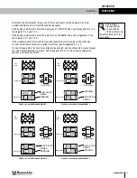
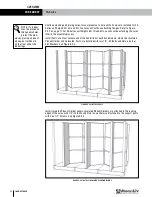
Determine the airflow paths for your job. The two airstreams are the Supply Air (air from
outside) and Return Air (air from the conditioned space).
If the Supply and Return Air enter the Core Array on OPPOSITE sides, use Arrangements 1 or 3.
(See Figures 2.0.0 and 2.0.2)
If the Supply and Return Air enter the Core Array on the SAME side, use Arrangements 2 or 4.
(See Figures 2.0.1 and 2.0.3)
If the airstreams enter the Core Array low, and leave the Core Array high (or the other way
around), this airflow orientation is called “crossflow.” Use Arrangements 1 or 2.
If one airstream enters the Core Array high and leaves high, and the other enters low and leaves
low, this airflow orientation “parallel.” Use Arrangements 3 or 4. This airflow configuration
requires a performance derate.
1
2
2
1
1
1
2
2
End View
Front View
"ARRANGEMENT 1"
OPPOSITE-SIDE ENTRIES
CROSS AIRFLOWS
2
2
1
1
Back View
View
Top
FACE PLATE
PANEL
1
OUT
2
IN
1
OUT
2
IN
1
IN
1
IN
2
OUT
2
OUT
OPENING
End View
1
1
1
1
2
2
2
2
1
1
2
2
"ARRANGEMENT 2"
SAME-SIDE ENTRIES
CROSS AIRFLOWS
View
Top
Back View
Front View
1
IN
1
IN
2
IN
2
IN
1
OUT
1
OUT
2
OUT
2
OUT
OPENING
FACE PLATE
PANEL
End View
1
View
Top
1
2
1
1
2
2
2
1
1
2
2
"ARRANGEMENT 3"
OPPOSITE-SIDE ENTRIES
PARALLEL AIRFLOWS
DERATE PERFORMANCE
Back View
Front View
1
IN
1
IN
2
OUT
2
OUT
1
OUT
1
OUT
2
IN
2
IN
FACE PLATE
PANEL
OPENING
End View
Top
View
1
2
2
1
1
2
2
1
2
1
1
2
"ARRANGEMENT 4"
SAME-SIDE ENTRIES
PARALLEL AIRFLOWS
DERATE PERFORMANCE
Back View
Front View
2
OUT
2
OUT
1
OUT
1
OUT
1
IN
1
IN
2
IN
2
IN
FACE PLATE
PANEL
OPENING
NOTE: Filters
are required but
are supplied by
others and must be
installed upstream of the
core arrays.
FIGURE 2.0.0 ASSEMBLY ARRANGEMENT 1
FIGURE 2.0.1 ASSEMBLY ARRANGEMENT 2
FIGURE 2.0.2 ASSEMBLY ARRANGEMENT 3
FIGURE 2.0.3 ASSEMBLY ARRANGEMENT 4
OPERATION


