


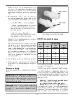
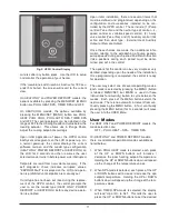


HPPH Control Display
The HPPH display is viewable from outside of the
heater. All operation and settings of the HPPH control
are accomplished through the use of the 3 buttons of
the user interface. These buttons are labeled as fol-
lows (see Fig. 5):
• MENU/SET – Scroll through available menus
and set changed values (MENU)
• UP – Increase values in adjustible menus
• DOWN – Decrease values in adjustible menus
The display uses a 2-line, 16-character backlit Liquid
Crystal Display (LCD) as the method for supplying
information. The backlight is normally off. The back-
light is on for 15 minutes after Power-Up and for 15
Water connections from the unit to the main return
line can be PVC pipe or flexible pipe approved for
the purpose and, in either case, should be at least
equal in size to the main pool/spa circulation pip-
ing.
4. Shut Off/Diverter valves, preferably three-way
valves which allows for a bypass route, on the
inlet and outlet lines of the HPPH are required if:
- water flow to the unit will exceed 60gpm
- to protect (completely bypass) the unit from
any harmful chemical treatments (i.e. Acid
wash, back-to-back super chlorinators, stain
treatments, etc.); or
- to be able to isolate the unit for
service/repair or freeze preparation and still
allow pool/spa circulation to continue
Please refer to the plumbing diagrams, starting on
pg. 40, for further instruction.
Please note that some municipalities do not allow
the use of a shut off valve on the effluent/outlet
side of any heating equipment, especially when
there is one on the inlet side. These entities typi-
cally instead allow a PVC tee and spring check
valve on the effluent/outlet side. This is allowed by
Raypak and can also double as your protection
from chemical feeders & chlorinators that our
downstream of the unit.
5. Operate the pump and check the system for leaks.
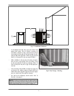
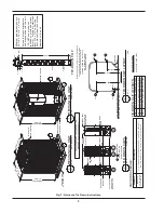
6. Drain plugs are located on each union fitting as
shown in Fig. 4 for draining the system during win-
terizing.
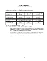
Pressure Drop
For system pressure drop information, refer to Table B
below.
10
Fig. 4: Water Connections/Drain Plugs
WATER IN
WATER OUT
Table B: Pressure Drop Across Heat Pump Pool Heater
Note: Multiply the pressure drop in psi by 2.3067 to yield the pres-
sure drop in Ft. H
2
O Head (TDH).
Flow
(gpm)
Pressure Drop
5450
6450/
6450HC
8450/
8450HC
30
4
6
9
40
7
9
9
50
10
10
10
60
11
11
11
70
12
12
12
80
13
13
13
CAUTION:
When the drain plugs are removed for
draining the system, ensure that they are stored in a
safe place for re-installation when needed to restart
the system.
NOTE:
While it is possible to mount the upper union
with the drain plug vertically, the manufacturer has
determined that installing both unions with the drain
plugs facing down as shown in Fig. 4 provides for the
best draining of the system.


