


4
INSTALLATION INSTRUCTIONS
water Piping
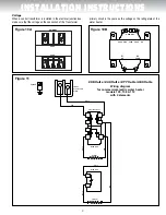
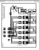
Refer to figure 2 for a typical installation. Use of this layout should pro-
vide a trouble-free installation for the life of the water heater. Refer to
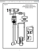
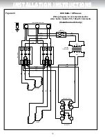
figures 3 to 9 for different installation configurations. Before making the
plumbing connections, locate the COLD water inlet and the HOT water
outlet, these fittings are both 1½” N.P.T. male thread. Install a shut-off
valves close to the water heater in the hot and cold water lines. It is recom-
mended that unions be installed in the hot and cold water lines so that the
water heater can be easily disconnected, if servicing is required. When
assembling the hot and cold piping, use a good food grade of pipe joint
compound, and ensure all fittings are tight. It is imperative that open flame
is not applied to the inlet and outlet fittings, as heat will damage or destroy
the plastic lined fittings. this will result in premature failure of the fit-
tings, which is not covered by the warranty.
temperature and Pressure-Relief valve
DANGER
WARNING
CAUTION
AVERTISSEMENT
ATTENTION
do not plug the temperature and pressure-relief valve or its dis-
charge line. do not remove the relief valve. Make sure the relief
valve is properly sized for the water heater. If the relief valve con-
tinuously discharges water, call a qualified service technician to
correct the problem. Failure to follow these instructions can result in
property damage, personal injury, or death.
In order to provide full protection against excess pressure and/or tem-
perature, a temperature & pressure-relief valve meeting the requirements
of the Standard Relief Valves and Automatic Gas Shut-Off Devices for
Hot Water Supply Systems, CSA 4.4, in Canada, and ANSI Z21.22, in
the United States is supplied with the water heater and Must be
installed by the installer. The relief valve should never be plugged or
removed from the opening marked for it on the water heater.
If this relief valve should need to be replaced, use only a new tempera-
ture and pressure-relief valve. Never install an old or existing relief valve,
as it may be damaged or inadequate for the working requirements of the
new water heater. This new relief valve must meet all local codes and
must have a maximum set pressure that does not exceed the hydro-
static working pressure of the water heater (150 psi = 1,035 kPa) and a
BTU/hr rating equal to or greater than the input rating, as shown on the
water heater rating plate. Never install another type of valve between the
relief valve and the water heater.
A discharge line must be installed into the relief valve. The discharge line:
• Must not be smaller than the outlet pipe size of the relief valve.
• Must not terminate less than six (6) inches (15.2 cm) and not more
than twelve (12) inches (30.5 cm) above a floor drain or drain pan con-
nected to an adequate free-flowing drain.
• Must not be restricted in any way. Do not thread, cap, or in any way
restrict the end of this outlet.
• Must be of a material capable of withstanding 210°F (99°C) without
distortion.
• Must be installed to allow complete drainage of the relief valve and
discharge line.
Vacuum B reaker
recommended
Thermal Expansion Tank
Temperature and
Pressure-Relief Valve
Overflow Tube
Union
Drain Pan
Manual shut-off Valve
C heck Valve
Drain
C OLD WATER
INLET
HOT WATER
OUTLET
INSTALL AS PER LOCAL CODES
INSTALLER SELON LES CODES LOCAUX
Union
Manual shut-off Valve
Casse-vide
recommandé
Réservoir d'expansion thermique
Soupape de sûreté
température et
pression
Tuyau d'évacuation
Raccord
Bassin de rétention
Robinet d'arrêt manuel
Clapet
de retenue
Drain
ENTRÉE
D'EAU FROIDE
SORTIE
D'EAU CHAUDE
Raccord
Robinet d'arrêt manuel
figure 2


