


PWM servo connection
Quad Plan PWM servo connection
SAGI-QP supports 4 channels of PWM multi-rotor ESC input, 6 channels of servo/ESC
input.
PWM output signal does not correspond to RC travel. PWM signal here is completely controlled by
the flight controller. You can ignore the radio control output sequence
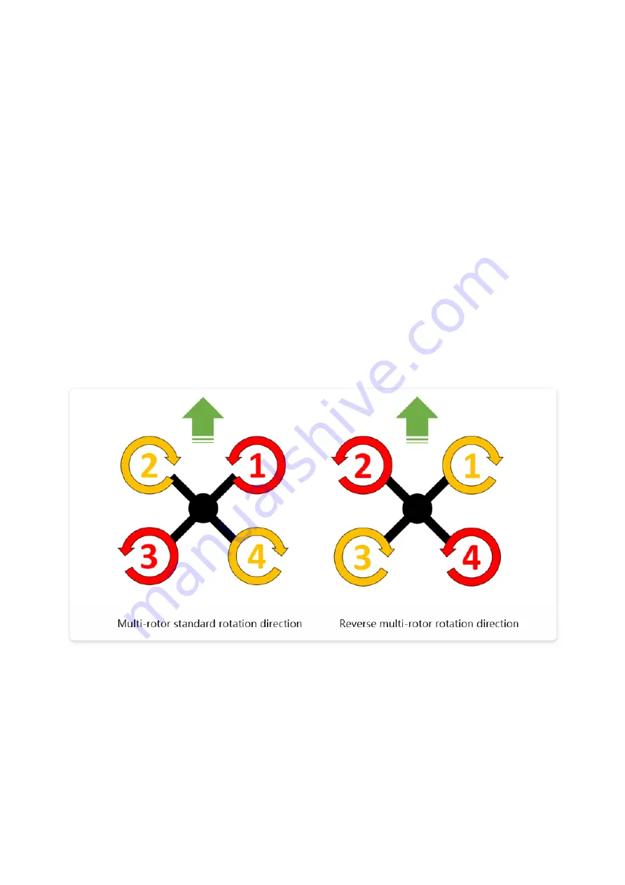
There are strict requirements for the ESC connection of the multi-rotor part. User
must remember that right front for PWM1, connect them in counterclockwise order,
which means followed by PWM2~PWM4. Usually, it only needs to connect the signal
cable and the GND cable. Does not need 5V power supply (except for the special
model ESC, it is forbidden to take power from the flight control).
Please connect the cable
【
18
】【
19
】【
20
】【
21
】
four PWM outputs in turn, and
well connect GND. (example: cable [2])
Firmware 2.0 or above supports X4 and X4R configuration. Please choose the correct
configuration according to your requirement.
Please calibrate the throttle range with the radio control before using ESC. Calibrate the range with
default setting. The standard range is 1100μs~1940μs. Fail to calibrate the throttle range will result
in a power system control failure, and the resulting defect or accident is artificial.
PWM 5~PWM 10 can be connected to the servo and fixed-wing ESC (or throttle
servo) according to custom and certain rules
Please keep in mind all ESC connection sequence for following parameter adjustment.