


8
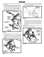
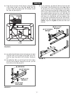
23. Position the flow control mounting bracket (figure 13).
a. Push on flow control arm until it locks in "OFF"
position.
b. Slide flow control mounting bracket along tube until
closure plate in bottom of hopper just closes.
c. Snug the 5/16" nylock hex nuts just enough to hold
flow control mounting bracket in place.
d. Set adjustable stop at "5". Pull flow control arm
against stop. Verify that closure plate has opened
about half way.
e. If closure plate does not open half way, adjust
position of flow control mounting bracket until
closure plate will open about half way at "5" and
will still close when arm is locked in "OFF" position.
Tighten
the 5/16" nylock hex nuts.
FIGURE 13
FIGURE 12
FLOw
CONTROL
ARM
OFF
ON
1
2
3
4
6
7
8
9
10
5
ADJUSTABLE
STOP
(SETTING "5")
ON
OFF
(Q) NYLON
WING NUT
OFF
ON
1
2
3
4
6
7
8
9
10
5
(J) 5/16" FLAT
WASHER
(I) NYLON
WASHER
(R) ADJUSTABLE
STOP
(E) 1/4" x 3/4"
CARRIAGE BOLT
ENGLISH
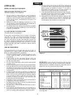
22. Place the adjustable stop (R) into the "ON" end of the slot
in the top of the flow control mounting bracket. Secure
with the 1/4" x 3/4" carriage bolt (E), a nylon washer (I),
a 5/16" flat washer (J) and the nylon wing nut (Q). See
figure 12.
Summary of Contents for 45-03291
Page 22: ...22 NOTES ...
Page 23: ...23 NOTES ...


