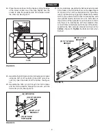
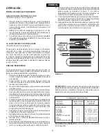
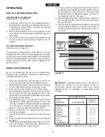
Agri-Fab 45-03291 Owner'S Manual Download Page 10

10

ENGLISH

FIGURE 17

   FERTILIZER

   Powder 

3 - 5 

3' - 4'

   Granular 

3 - 5 

8' - 10'

   Pelleted 

3 - 5 

10' - 12'

   Organic 

6 - 8 

6' - 8'

   GRASS SEED

   Fine 

3 - 4 

6' - 7'

   Coarse 

4 - 5 

8' - 9'

   ICE MELTER 

6 - 8 

10' - 12'

   TYPE 


SPREAD

   MATERIAL 

FLOW SETTING 

WIDTH

APPLICATION CHART

OPERATING SPEED 

- 3 MPH. (100 ft. in 23 seconds)

IMPORTANT:

    Application  rates  shown  in  the  chart  are 

affected  by  humidity  and  by  the  moisture  content  of 
the  material  (granular  and  pellet).  Some  minor  setting 
adjustments  may  be  necessary  to  compensate  for  this 

condition.

OVERLAP

REFER 

TO

CHARTS

USING YOUR SPREADER

We  do  not  recommend  the  use  of  any  powdered  lawn 
chemicals,  due  to  difficulty  in  obtaining  a  satisfactory  or 
consistent broadcast pattern.

1.  Determine approximate square footage of area to be 

covered and estimate amount of material required.

2.  Before filling the hopper make sure the flow control arm 

is in the off position and the closure plate is shut.

3.  Break up any lumpy fertilizer as you fill the hopper.
4.  Set the adjustable stop with the flow control arm still in 

the off position. Refer to the application chart on this 
page and to the instructions on the fertilizer bag to select 
the proper flow rate setting.

5.  The  application  chart  is  calculated  for  light  to  heavy 

application at a vehicle speed of 3 mph, or 100 ft. in 23 
seconds. A variation in speed will require an adjustment 
of  the  flow  rate  to  maintain  the  same  coverage. The 
faster you drive, the wider the broadcast width.

6.  Make sure the drive pin is installed in the axle before 

starting the spreader.

7.  Always start the tractor in motion before opening closure 

plate. 

8.  Always shut the closure plate before turning or stopping 

the tractor.

9.  If fertilizer is accidentally deposited too heavily in a small 

area, soak the area thoroughly with a garden hose or 
sprinkler to prevent burning of the lawn.

OPERATION

10.  To insure uniform coverage, make each pass so that the 

broadcast pattern slightly overlaps the pattern from the 
previous pass as shown in figure 17. The approximate 
broadcast widths for different materials are shown in 
the application chart on this page.

11.  When broadcasting weed control fertilizers, make sure 

the  broadcast  pattern  does  not  hit  evergreen  trees, 
flowers or shrubs.

12.  Heavy moisture conditions may require a cover over the 

hopper to keep contents dry.  The vinyl cover acts as a 
wind and moisture shield, but should not be used as a 

rain cover.

HOw TO USE YOUR SPREADER 

SETTING THE FLOw CONTROL

(Refer to figure 13 on page 8.)

1.  Loosen the nylon wing nut, set the adjustable stop to 

the desired flow rate setting and retighten the wing nut. 
The higher the setting number, the wider the opening 
in the bottom of the hopper.

2.  Refer to the application chart on this page and to the 

instructions on the fertilizer bag to select the proper flow 

rate setting.

3.  Pull  the  flow  control  arm  against  the  adjustable  stop 

for the on position and toward the hopper for the off 

position.

THE FREE wHEELING FEATURE

(Refer to figure 4 on page 6.)

The spreader is equipped with a removable pin in the left 
(drive) wheel. Remove the pin to disengage the drive wheel 
so that the axle, gears and spreader plate do not rotate. With 
the drive wheel disengaged, the spreader may be towed at 
speeds up to 20 mph. If the drive wheel is engaged do not 
exceed 6 mph.

Summary of Contents for 45-03291

Page 1: ...TION Lire et suivre attentivement les instructions et consignes de sécurité de cette notice PRECAUCION Lea cuidadosamente los Procedimientos e Instrucciones para la Operación Segura de la Máquina Safety Assembly Operation Maintenance Parts Seguridad Montaje Operación Mantenimiento Piezas de Repuesto Sécurité Assemblage Fonctionnement Maintenance Pièces de Rechange PRINTED IN USA the fastest way to...

Page 2: ... Enganche 8 Tubo de Enganche 9 Soporte de Montaje del Control de Flujo 10 Brazo del Control de Flujo 11 Tapa de la Tolva 12 Malla Paquete de Elementos de Ferretería vea la página 3 CARTON CONTENTS Loose Parts in Carton CONTENIDO DE LA CAJA Partes Sueltas en la Caja CONTENU DU CARTON Pièces en Vrac Dans le Carton FRANÇAIS ESPAÑOL ENGLISH 1 Trémie 2 Entretoises d attelage 3 Bielle de contrôle de déb...

Page 3: ...nk V 1 Drive Pin KEY QTY DESCRIPTION A 4 Hex Bolt 5 16 x 1 3 4 B 6 Hex Bolt 1 4 x 1 3 4 C 2 Hex Bolt 3 8 x 3 4 D 2 Hex Bolt 1 4 x 1 E 1 Carriage Bolt 1 4 x 3 4 F 8 Nylock Hex Nut 1 4 G 4 Nylock Hex Nut 5 16 H 2 Nylock Hex Nut 3 8 I 4 Nylon Washer J 7 Flat Washer 5 16 K 4 Flat Washers 3 4 KEY QTY DESCRIPTION E F D C B A J K L G H I M N O P Q R NOT SHOWN FULL SIZE SHOWN FULL SIZE U T V S ...

Page 4: ...nyone to ride or sit on spreader attachment frame Never allow children to operate the tractor or spreader attachment and do not allow adults to operate without proper instructions Alwaysbeginwiththetransmissioninfirst low gearand with the engine at low speed and gradually increase speed as conditions permit When towing broadcast spreader do not drive too close to a creek or ditch and be alert for ...

Page 5: ...n the spreader upside down as shown in figure 1 2 Removethelocknutfromthemiddleboltinthecrossover tube and shaft support plate Leave the bolt in place See figure 1 3 Assemble the hitch tube onto the middle bolt and secure itwiththesamelocknutyouremoved DONOTTIGHTEN YET See figure 1 IMPORTANT The hitch tube must attach to the side of the crossover tube opposite the shaft support plate CROSSOVER TUB...

Page 6: ... lock the pin in place See figure 4 FIGURE 7 16 Assemble the flow control mounting bracket to the flow control mounting tube using two 5 16 x 1 3 4 hex bolts A four 5 16 flat washers J and two 5 16 nylock hex nuts G DO NOT TIGHTEN YET See figure 7 G 5 16 NYLOCK HEX NUT A 5 16 x 1 3 4 HEX BOLT J 5 16 FLAT WASHER OFF ON 1 2 3 4 6 7 8 9 10 5 V DRIVE PIN AIR VALVE P SPACER K 3 4 FLAT WASHER M 1 8 x 1 ...

Page 7: ...n carefully The flow control arm should be snug but should pivot with no more than slight resistance See figure 9 17 Assemble the vinyl grip T onto the flow control arm See figure 8 18 Insert the flow control arm down through the slot in the flow control bracket Assemble the small hole of the flow control link U to the flow control arm using a 1 4 x 1 hex bolt D a nylon washer I and a 1 4 nylock h...

Page 8: ... open half way adjust position of flow control mounting bracket until closure plate will open about half way at 5 and will still close when arm is locked in OFF position Tighten the 5 16 nylock hex nuts FIGURE 13 FIGURE 12 FLOw CONTROL ARM OFF ON 1 2 3 4 6 7 8 9 10 5 ADJUSTABLE STOP SETTING 5 ON OFF Q NYLON WING NUT OFF ON 1 2 3 4 6 7 8 9 10 5 J 5 16 FLAT WASHER I NYLON WASHER R ADJUSTABLE STOP E ...

Page 9: ...as shown at the bottom of figure 16 Tighten the bolts and nuts when finished FIGURE 16 F 1 4 NYLOCK HEX NUT B 1 4 x 1 3 4 HEX BOLT 24 Place the screen down into the hopper sliding the edge of the screen under one of the clips Slightly bow the screen to slide the opposite side of the screen under the other clip See figure 14 FIGURE 14 25 Assemblethehitchbrackettothehitchextensionbracket using two 3...

Page 10: ...inmotionbeforeopeningclosure plate 8 Always shut the closure plate before turning or stopping the tractor 9 Iffertilizerisaccidentallydepositedtooheavilyinasmall area soak the area thoroughly with a garden hose or sprinkler to prevent burning of the lawn OPERATION 10 To insure uniform coverage make each pass so that the broadcast pattern slightly overlaps the pattern from the previous pass as show...

Page 11: ...embled mark down the positions of the parts as theyareremoved Thedrivewheelandsprocketpositions in relation to the slotted gear determine which direction the spreader plate will spin Be sure to reassemble them in their original positions Refer to figure 4 on page 6 Use shim washers Ref no 21 on pages 20 and 21 as needed for minimum backlash Add grease to gear and sprocket SERVICE AND ADJUSTMENTS S...

Page 12: ...o del vehículo relativas a la operaciónseguraencolinas Manténgasealejadodecolinas empinadas Siga las instrucciones de mantenimiento y lubricación según se describen en este manual ESPAÑOL OBSERVE ESTE SIMBOLO PARA INDICAR PRECAUCIONES IMPORTANTES DE SEGURIDAD SIGNIFICA ATENCION ESTE ALERTA ESTA INVOLUCRADA SU SEGURIDAD REGLAS PARA OPERACIONES SEGURAS Recuerde cualquier equipo motorizado puede caus...

Page 13: ...r Si existe interferencia con la parte trasera del vehículo ensamble el soporte de extensión de enganche según se muestra en la parte inferior de la figura 16 Cuando termine apriete los pernos y las tuercas 4 Instaleloscuatropuntalesdeengancheenelinteriordelmarco de la tolva dos a cada lado usando un perno hexagonal B y una tuerca de cierre hexagonal F a cada lado NO APRIETE TODAVIA Vea la Figura ...

Page 14: ...a graduación adecuada para la tasa de flujo 5 El cuadro de aplicación está calculado para una aplicación de ligera a pesada a una velocidad del vehículo de 3 MPH 4 8 km h sea 30 metros en 23 segundos Cualquier variación de la velocidad requerirá un ajuste de la tasa de flujo para mantener el mismo cubrimiento A mayor velocidad más amplia será la anchura del lanzado 6 Asegúrese de que la clavija de...

Page 15: ... y el engranaje 6 Aceite los bujes de nylon en el eje vertical de la rueda dentada y en el eje de las ruedas por lo menos una vez al año o con más frecuencia si es necesario 7 Aceite el cojinete de la rueda derecha engranaje libre por lo menos una vez al año o con más frecuencia según sea necesario ALMACENAMIENTO 1 Laveelinteriordelatolvayelexteriordelesparcidoryséquelos bien antes de guardar la u...

Page 16: ... et gazons Ne jamais conduire le tracteur et l épandeur sans porter des chaussures adéquates Ne transportez jamais personne sur l attelage de l épandeur Ne laissez jamais d enfants utiliser le tracteur ni la remorque et ne laissez aucun adulte utiliser le tracteur ni la remorque sans lui avoir fourni auparavant les instructions adéquates Commencez toujours en veillant à ce que le levier de la tran...

Page 17: ...trôlededébitdel épandeur Si ces pièces ne gènent pas l arrière du véhicule montez la pièce de rallonge de support d attelage comme illustré au bas de la figure 16 Serrez les boulons et les écrous après avoir terminé FRANÇAIS 4 Fixez les quatres entretoises d attelage à l intérieur du cadre de la trémie en utilisant le boulon hex B et le contre écrou hex F de chaque côté NE PAS SERRER POUR L INSTAN...

Page 18: ...RE ÉPANDEUR AÉRATEUR RÉGLAGE DU DÉBIT Reportez vous à la figure 13 de la page 8 1 Desserrezl écrouàoreillesennylonetréglez labutéeréglable surledébitdésiréetresserrezl écrouàoreilles Plusleréglage est haut et plus l ouverture au fond de la trémie sera large 2 Reportez vous au tableau de la page 18 et aux instructions figurant sur l emballage de l engrais afin de déterminer le réglage du débit 3 Ti...

Page 19: ...u NETTOYAGE 4 Rincez l intérieur de la trémie et l extérieur de l épandeur et séchez le tout avant de le ranger LUBRIFICATION voir figure 18 5 Appliquezunpeudegraissepourautomobilessurlacouronne et l engrenage si nécessaire 6 Huilez les fourrures en nylon de l arbre vertical de la couronne ainsi que l essieu au moins une fois par an ou plus souvent si nécessaire 7 Huilez le roulement droit baladeu...

Page 20: ...7 23 33 59 27 26 28 3 19 36 9 9 46 9 57 9 40 14 17 37 37 24 50 13 9 65 29 5 4 9 35 35 E 6 52 32 7 C 29 40 53 25 E 1 39 10 31 2 39 40 58 55 56 58 49 40 B 61 9 B D 16 63 42 44 8 37 9 7 48 A 13 41 60 47 62 7 45 58 39 39 39 54 9 54 49 50 11 51 64 54 15 9 A 13 11 54 54 34 OF F ON 1 2 3 4 6 7 8 9 10 5 35 38 30 ...

Page 21: ...tor 32 43070 5 Washer Flat 3 8 33 43054 2 Bolt Hex 3 8 16 x 2 Lg 34 48586 1 Rod Flow Control REF PART QTY DESCRIPTION NO NO 35 23525 4 Brace Hitch 36 23762 1 Shaft Support Plate 37 1509 69 6 Bolt Hex 1 4 20 x 1 3 4 38 47441 1 Screen 39 1543 69 12 Washer Nylon 40 43088 15 Washer Flat 1 4 Std 41 24858 1 Stop Adjustable 42 24915 1 Bracket Flow Control Mount 43 62474 1 Gear Assembly 44 24917 1 Flow Co...

Page 22: ...22 NOTES ...

Page 23: ...23 NOTES ...

Page 24: ...REPAIR PARTS Agri Fab Inc 809 South Hamilton Sullivan IL 61951 217 728 8388 www agri fab com the fastest way to purchase parts www speedepart com 2002 Agri Fab Inc ...

Reviews: