


11
CHECK FOR LOOSE FASTENERS
1.
Before each use make a thorough visual check of the
spreader for any bolts and nuts which may have loosened.
Retighten any loose bolts and nuts.
CHECK FOR wORN OF DAMAGED PARTS
2. Check for worn or damaged parts before each use.
Repair or replace parts if necessary.
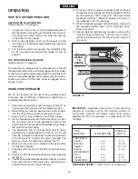
CHECK TIRE INFLATION
3. Check if tires are adequately inflated before each use. Do
not inflate beyond maximum recommended pressure.
CLEANING
FIGURE 18
1. Rinse inside of hopper and exterior of spreader and dry
off before storing.
2. Store in a clean, dry area.
CAUTION: DO NOT
inflate tires beyond the
maximum recommended pressure printed on
side of tire.
4. Rinse inside of hopper and exterior of spreader and dry
off before storing.
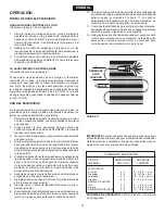
LUBRICATE
(See figure 18)
5. Lightly apply automotive grease as needed to the
sprocket and gear.
6. Oil the nylon bushings on the vertical sprocket shaft
and on the axle at least once a year, or more often as
needed.
7. Oil right hand (idler) wheel bearing at least once a year
or more often as needed.
MAINTENANCE
GREASE
OIL
OIL
STORAGE
ENGLISH
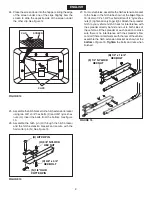
REPLACING SLOTTED GEAR
1. If the axle, slotted gear and sprocket assembly is
disassembled, mark down the positions of the parts as
they are removed. The drive wheel and sprocket positions
in relation to the slotted gear determine which direction
the spreader plate will spin. Be sure to reassemble them
in their original positions. (Refer to figure 4 on page 6.)
Use shim washers (Ref. no. 21 on pages 20 and 21)
as needed for minimum backlash. Add grease to gear
and sprocket.
SERVICE AND ADJUSTMENTS
SHAFT SUPPORT PLATE
SLOTTED GEAR
LOCKED UP SPREADER
1. Turn the spreader over so that the wheels are off the
ground.
2. Loosen all three nuts on the shaft support plate just
enough so that the bolts can be turned easily with a
wrench but cannot be turned by hand.
3. Spin the drive wheel and note how freely it spins and
how much noise the slotted gear makes.
4. To free up the wheel and gear, tap gently on the front
or rear edge of the shaft support plate to move it
slightly forward or backward. You can also tap at the
corners of the plate to angle it slightly.
5. Spin the drive wheel after each adjustment to see if it
spins more freely and if the gear noise is reduced.
6. Continue making slight adjustments until you find the
position where the drive wheel spins most freely and
the gear makes the least noise.
7. Secure the shaft support plate in this position by
retightening all three nuts that you loosened.
FIGURE 19
Summary of Contents for 45-03291
Page 22: ...22 NOTES ...
Page 23: ...23 NOTES ...


