background image

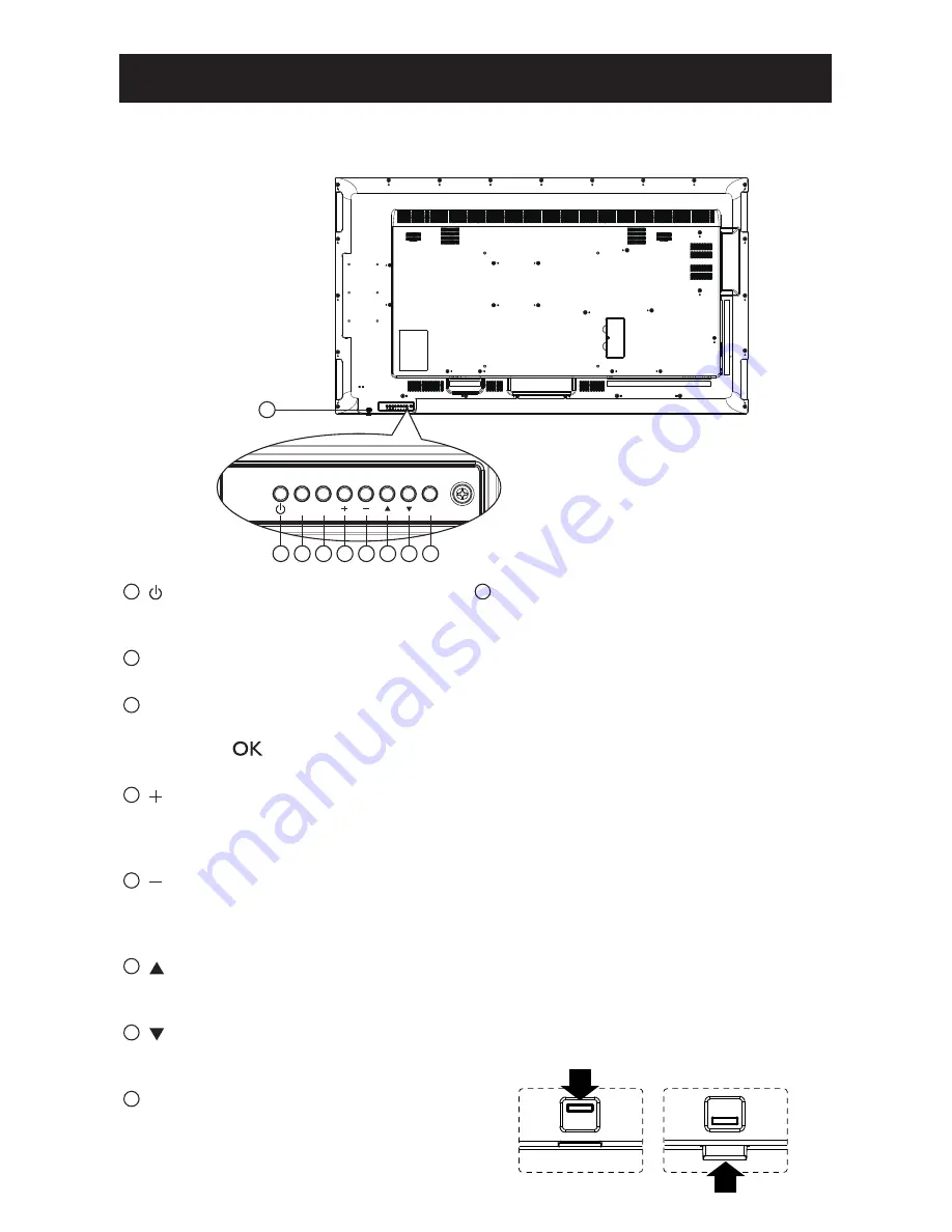
2.1.  Control Panel

1

2

3

4

5

6

7

8

MUTE INPUT

MENU

9

1

 [ ] Power button

Use this button to turn the display on or put 

the display to standby.

2

 [MUTE] button

Switch the audio mute ON/OFF.

3

 [INPUT] button

Choose the input source.
•  Used as [

] button in the On-Screen-

Display menu.

4

 [ ] button

Increase the adjustment while OSD menu is 

on, or increase the audio output level while 

OSD menu is off.

5

 [ ] button

Decrease the adjustment while OSD menu is 

on, or decrease the audio output level while 

OSD menu is off.

6

 [ ] button

Move the highlight bar up to adjust the 

selected item while OSD menu is on.

7

 [ ] button

Move the highlight bar down to adjust the 

selected item while OSD menu is on.

8

 [MENU] button

Return to previous menu while OSD menu is 

on, or to activate the OSD menu when OSD 

menu is off.

9

  Remote control sensor and power status 

indicator

•  Receives command signals from the remote 

control.

•  Indicates the operating status of the display 

without OPS: 


-

Lights green when the display is turned 

on


-

Lights red when the display is in standby 

mode


-

Lights amber when the display enters 

APM mode


-

If the light blinks red, it indicates that a 

failure has been detected


-

Lights off when the main power of the 

display is turned off

•  Pull down the lens to have better remote 

control performance and easy to observe 

the light information of power status.

•  Push up the lens before mounting the 

display for video wall application.

•  Pull/Push the lens until hearing the click 

sound.


11

CHAPTER 2: PARTS AND FUNCTIONS

Summary of Contents for PM-65P

Page 1: ......

Page 2: ...ol 14 2 3 3 Inserting the batteries in the remote control 15 2 3 4 Handling the remote control 15 2 3 5 Operating range of the remote control 15 CHAPTER 3 CONNECTING EXTERNAL EQUIPMENT 16 3 1 Connecti...

Page 3: ...NA DMP 24 4 5 3 How to use DLNA DMR from PC 25 4 6 Play multimedia files from USB device 27 4 7 Play options 27 4 7 1 Playing music files 27 4 7 2 Playing movie files 28 4 7 3 Playing photo files 28 C...

Page 4: ...ug the display if you need to clean it with a slightly damp cloth The screen may be wiped with a dry cloth when the power is off However never use organic solvent such as alcohol or ammonia based liqu...

Page 5: ...ce personnel Keep the display out of direct sunlight and away from stoves or any other heat sources Remove any object that could fall into the vents or prevent proper cooling of the display s electron...

Page 6: ...igital device pursuant to part 15 of the FCC Rules These limits are designed to provide reasonable protection against harmful interference when the equipment is operated in a commercial environment Th...

Page 7: ...s electrical installation should have a reserve short circuit protection device in the form of a fuse with a nominal value no larger than 16 amperes A To completely switch off the equipment the power...

Page 8: ...n this type of plug proceed as follows 1 Remove fuse cover and fuse 2 Fit new fuse which should be a BS 1362 5A A S T A or BSI approved type 3 Refit the fuse cover If the fitted plug is not suitable f...

Page 9: ...E UTSTYRET PLASSERES M DU PASSE P AT KONTAKTENE FOR ST MTILF RSEL ER LETTE N End of Life Disposal Your new Public Information Display contains materials that can be recycled and reused Specialized com...

Page 10: ...ated diphenyl ethers in concentrations exceeding 0 1 weight and 0 01 weight for cadmium except for the exemptions set in Schedule 2 of the Rule E Waste Declaration for India This symbol on the product...

Page 11: ...PTIONS ADJUST VOL NORMAL ID ID SET ENTER Video Signal Cable D SUB to D SUB Cable Daisy chain cable NOTES For all other regions apply a power cord that conforms to the AC voltage of the power socket an...

Page 12: ...e base mounting kit Failure to follow correct mounting procedures could result in damage to the equipment or injury to the user or installer Product warranty does not cover damage caused by improper i...

Page 13: ...ake or other natural disaster be sure to consult the bracket manufacturer for installation location Ventilation Requirements for enclosure locating To allow heat to disperse leave space between surrou...

Page 14: ...tem while OSD menu is on 8 MENU button Return to previous menu while OSD menu is on or to activate the OSD menu when OSD menu is off 9 Remote control sensor and power status indicator Receives command...

Page 15: ...H Internal speaker on off switch 17 AUDIO IN Audio input from external AV device RCA 18 AUDIO OUT Audio output to external AV device 19 USB PORT Connect your USB storage device 20 SPEAKERS OUT Audio o...

Page 16: ...choose items 7 button Confirm an entry or selection 8 ADJUST button Access currently available options picture and sound menus 9 MUTE button Press to turn the mute function on off 10 COLOR buttons Ch...

Page 17: ...press 0 and 1 for display No 1 press 1 and 1 for display No 11 The numbers available are from 01 255 2 Not pressing any button within 10 seconds will exit the ID Mode 3 If an error pressing of button...

Page 18: ...ery acid as it can damage your skin NOTE If you do not intend to use the remote control for a long period remove the batteries 2 3 4 Handling the remote control Do not subject to strong shock Do not a...

Page 19: ...DVD VCR VCD 3 1 1 Using COMPONENT video input DVD VCR VCD AUDIO IN COMPONENT IN YPbPr COMPONENT Out YPbPr Audio Out 3 1 2 Using Video Source input DVD VCR VCD Y CVBS IN Y CVBS Out AUDIO IN CHAPTER 3...

Page 20: ...3 1 3 Using HDMI video input DVD VCR VCD HDMI Out HDMI IN 3 2 Connecting a PC 3 2 1 Using VGA input PC VGA IN VGA AUDIO IN VGA Out D Sub 15 pin Audio Out CONNECTING EXTERNAL EQUIPMENT 17...

Page 21: ...2 2 Using DVI input PC VGA AUDIO IN DVI Out Audio Out DVI IN 3 2 3 Using HDMI input PC HDMI Out HDMI IN 3 2 4 Using DisplayPort input PC DisplayPort Out DisplayPort IN CONNECTING EXTERNAL EQUIPMENT 1...

Page 22: ...ple Displays in a Daisy chain Configuration You can interconnect multiple displays to create a daisy chain configuration for applications such as a video wall NOTE Maximum 25 displays 5x5 can be used...

Page 23: ...Connect the DVI OUT VGA OUT connector of DISPLAY 1 to the DVI IN connector of DISPLAY 2 PC DVI IN DVI DVI VGA OUT DVI IN DISPLAY 1 DISPLAY 2 Connect the DP OUT connector of DISPLAY 1 to the DP IN conn...

Page 24: ...D 3 4 3 Analog video connection Connect the DVI OUT VGA OUT connector of DISPLAY 1 to the VGA IN connector of DISPLAY 2 PC DISPLAY 1 DISPLAY 2 VGA IN VGA DVI VGA OUT VGA IN 3 5 IR connection IR IN Ext...

Page 25: ...RJ 45 RJ 45 ROUTER INTERNET To setup the network 1 Switch on the router and switch on its DHCP setting 2 Connect the router to this display with an Ethernet cable 3 Press HOME button to display the OS...

Page 26: ...cted in the Picture menu 4 3 Display the classic 4 3 format 4 3 Choose your Preferred Picture Settings 1 While this display is playing video source press ADJUST button 2 Press or button to choose Pict...

Page 27: ...h on your computer and the router Single display setup PC RJ 45 RJ 45 ROUTER Multiple display setup PC RJ 45 RJ 45 RJ 45 ROUTER DISPLAY 1 DISPLAY 2 NOTE If the apparatus does not return to DLNA mode d...

Page 28: ...stream We suggest to use DLNA DMP function via wired network for the sake of higher security and sufficient network bandwidth 4 5 3 How to use DLNA DMR from PC 1 Press HOME button Choose Network Setti...

Page 29: ...rk discovery 8 Now go to the directory of your media files Choose the media file by right click On the submenu from Play To You can find all displays connected to your network Choose the display and c...

Page 30: ...music files 1 Choose Music in the top bar Music 2 Choose one music track and press button To play all the tracks in a folder choose one music file Then press to Play All To skip to the next or previou...

Page 31: ...ose Repeat to play the video file repeatedly or Play once to play the video file once Status To view information about a video for example played position duration title or date 4 7 3 Playing photo fi...

Page 32: ...tem or to adjust its value Press button to confirm 4 Press BACK button to go back to the previous menu layer 5 Press HOME button to exit the OSD menu Using the display s control buttons 1 Press button...

Page 33: ...verification Colour Adjust the colour saturation of the picture Sharpness Adjust the sharpness of the picture Noise reduction Choose the amount of noise reduction for the picture MPEG artifact reducti...

Page 34: ...ough HDMI choose Computer Make sure that Format and edges Picture format Unscaled is selected so as to view maximum detail Format and edges Picture format Change the picture format See page 23 for the...

Page 35: ...cture Sound Tiling General settings Network settings With this function you can create a single large screen matrix video wall that consists of up to 100 sets of this display up to 10 sets on the vert...

Page 36: ...Position Frame comp Choose to turn the frame compensation function on or off If selected On the display will adjust the image to compensate for the width of the display bezels in order to accurately...

Page 37: ...ction allows you to program up to 7 different scheduled time intervals for this display to activate You can set Which input source the display will use for each scheduled activation period The time fo...

Page 38: ...f Source USB is chosen You need to set playliist Status Source On time Off time Repeat modes Playlist setting Schedule 1 Schedule 2 Schedule 3 Schedule 4 Schedule 5 Schedule 6 Schedule 7 USB HDMI 1 HD...

Page 39: ...at modes Playlist setting Schedule 1 Schedule 2 Schedule 3 Schedule 4 Schedule 5 Schedule 6 Schedule 7 No repeat Every Sunday Every Monday Every Tuesday Every Wednesday Every Thursday Every Friday Eve...

Page 40: ...ze the display of VGA input image NOTE This item is functional for VGA input only Local KB lock Choose to enable or disable the keyboard control buttons function of the display Unlock Enable the keybo...

Page 41: ...rd is connected to a wall outlet Last status The display will return to the previous power status on off standby when removing and replacing the power cord LED Choose Off to turn off the indicator Swi...

Page 42: ...eneral settings Network settings View network settings View connected network status Network Configuration Network configuration Choose how this display should assign addresses to the network resource...

Page 43: ...3d MKV MPEG 4 ASP 1920x1080 25p 30p 50i 60i 30 MPEG 1 L1 L2 MPEG 1 2 2 5 L3 AC3 E AC3 WMA H 264 1920x1080 30 USB Multimedia Formats File Extensions Container Video codec Maximum resolution Frequency k...

Page 44: ...480 29 97 Hz 13 5 MHz 4 3 Modified NTSC Standard 480p 59 94 Hz 27 MHz 576i 720 576 25 Hz 13 5 MHz 4 3 Modified PAL Standard 576p 50 Hz 27 MHz HDTV Resolution Standard Resolution Active Resolution Refr...

Page 45: ...power saving mode or cable connections The display settings table complies to the IBM VESA standards and based on the analog input The DVI support mode is regarded as same to the PC support mode The b...

Page 46: ...n 3 If the image exceeds the screen size Scan Mode may need to be set to Underscan Use the Zoom mode or Custom zoom function in the Screen menu to fine tune display geometry and time frequency paramet...

Page 47: ...t HDMI Jack x 2 Type A 19 pin Digital RGB TMDS Video Audio MAX Video 720p 1080p 1920 x 1080 60 Hz WUXGA Audio 48 KHz 2 Channel L R Supports LPCM only DVI D Input DVI D jack Digital RGB TMDS Video VGA...

Page 48: ...ption W 0 50 W Off Mode Power Consumption W 0 50 W Display Resolution Pixels 1920 x 1080p Network Standby W 16W Environmental Condition PM 65P Temperature Operational 0 40 C Storage 20 60 C Humidity O...

Reviews: