


87
Selecting Test Features - SONET Operation
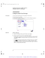
Adding Pointer Adjustments
Description
The transmitted SPE or VT pointer value can be adjusted for testing purposes.
HOW TO:
1
Set up the SONET transmit interface and payload required. See "Setting
Transmit Interface " page 60.
2
Choose the POINTER TYPE.
3
Choose the ADJUSTMENT TYPE required.
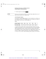
BURST - You determine the size of the burst by the number of PLACES chosen.
If, for example, you choose 5 PLACES the pointer value will be stepped 5 times
in unit steps e.g. 0 (start value), 1, 2, 3, 4, 5 (final value). The interval between
steps is as follows:
For STS-SPE the minimum spacing between adjustments is 4 frames (500 ns).
For VT the minimum spacing between adjustments is 4 multiframes (2 ms).
Choose ADJUST POINTER [ON] to add the chosen burst.
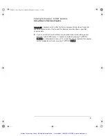
NEW POINTER - You can choose any pointer value in thedefined range
(0 to 782 For an STS-1 pointer) with or without a New Data Flag, and transmit it.
The current pointer value is displayed for information purposes.
Choose ADJUST POINTER [ON] to transmit the new pointer value.
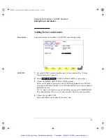
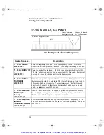
OFFSET - You can frequency offset the line rate or the SPE/VT rate, relative to
each other, thus producing pointer movements. If you offset the SPE pointer, an
87:3 sequence of pointer movements is generated. The available configurations
are listed in the following table.
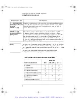
If you are currently adding Frequency Offset to the SONET interface or payload,
pointer OFFSET is not available.
SONET_Usr.bk Page 87 Wednesday, December 13, 2000 11:11 AM
Artisan Technology Group - Quality Instrumentation ... Guaranteed | (888) 88-SOURCE | www.artisantg.com


