


80
E5505A Installation Guide
6
Preventive Maintenance
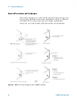
Half-Rack-Width Instrument
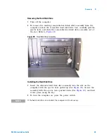
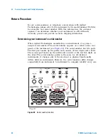
To remove a half-width instrument from a system rack
1
Power off the system.
•
For details see the system installation
guide.
2
Remove the selected instrument’s power cord
from the power strip in the rack.
3
The instrument is attached to the half-rack width
instrument beside it; remove that instrument’s
power cord from the power strip also.
•
The instruments are secured together
by lock links at the front and rear. The
lock links at the rear attach with screws.
The lock links at the front hook together.
4
Remove the power cord and other cables from the
front and rear of both instruments.
•
Note the location of cables for
re-installation.
5
Remove the four corner screws on the front of the
rack panel that secures the instruments in place.
•
The screws are located near the corners
of the face of the instrument.
•
Use a #2 Phillips screwdriver.
6
Slide both instruments, as a single unit, out from
the front of the rack and set them on a secure, flat
surface.
7
Detach the lock links that secure the rear of the
instruments together by removing their screws.
•
Use a #2 POZIDRIV screwdriver.
•
8
Carefully and at the same time, push one
instrument forward and pull the other back to
unhook the lock links that secure the front of the
instruments to each other.
9
Store the “partner” instrument and lock links
while the selected instrument is out of the rack.
•
Only install the instruments as a pair;
individual installation is not secure.
Summary of Contents for E5505A
Page 18: ...18 E5505A Installation Guide 1 General Information ...
Page 22: ...22 E5505A Installation Guide 2 Flat Panel Display ...
Page 30: ...30 E5505A Installation Guide 3 System Interconnections ...
Page 84: ...84 E5505A Installation Guide 6 Preventive Maintenance ...
Page 96: ...96 E5505A Installation Guide A Service Support and Safety Information ...


