


Chapter 7
7-73
Programming Examples
Measurement Process Synchronization Examples
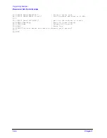
• If bit 5 in the event-status register is not set, the program prints:
SYNTAX ERROR BIT
NOT SET
.
• The SRQ interrupt is re-enabled on the bus.
• At the finish, the interrupt is deactivated.
• The analyzer is released from remote control and the program ends.
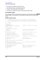
Running the Program
Run the program. The computer will preset the analyzer, then pause for a second or two.
After pausing, the program sends an invalid command string
“STIP 2 GHZ;”
to cause a
syntax error. This command is intended to be
“STOP 2 GHZ;”
. The computer will display a
series of messages from the SRQ-handler routine. The analyzer will display
CAUTION:
SYNTAX ERROR
and the incorrect command, pointing to the first character it did not
understand.
The SRQ can be cleared by reading the event-status register and clearing the latched bit,
or by clearing the enable registers with
CLES
. The syntax-error message on the analyzer
display can only be cleared by the GPIB Device Clear (DCL) message or Selected Device
Clear (SDC) message. Device Clear is not commonly used because it clears every device on
the bus. Selected Device Clear can be used to reset the input and output queue and the
registers of a specific instrument on the bus. This will also clear all the interrupt
definitions.
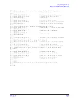
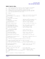
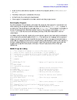
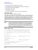
BASIC Program Listing
10
! This program is an example of using an SRQ based interrupt to
20
! detect an error condition in the analyzer. In this example, a
30
! syntax error is generated with an invalid command. The status byte
40
! is read in and tested. The error queue is read, printed out and
50
! then cleared.
60
!
70
! EXAMP4B
80
!
90
ASSIGN @Nwa TO 716
! Assign an I/O path for the analyzer
100 !
110 CLEAR SCREEN
120 ! Initialize the analyzer
130 ABORT 7
! Generate and IFC (Interface Clear)
140 CLEAR @Nwa
! SDC (Selective Device Clear)
150 OUTPUT @Nwa;"OPC?;PRES;"
! Preset the analyzer and wait
160 ENTER @Nwa;Reply
! Read the one from the analyzer
170 !
180 DIM Error$[50]
! String for analyzer error message
190 ! Set up syntax error interrupt
200 OUTPUT @Nwa;"CLES;"
! Clear the status registers
210 !
220 ! Generate SRQ when bit 5 is set
230 OUTPUT @Nwa;"ESE 32;"
! Event status register bit 5 enabled
240 !
250 ! Generate bit 5 in status register when syntax error occurs
260 OUTPUT @Nwa;"SRE 32;"
! Status register bit 5 enabled
270 !
280 ! Setup the interrupt pointer to a subroutine
290 ON INTR 7 GOSUB Srq_det
! When interrupt occurs go to Srq_det
Summary of Contents for 8719ES
Page 15: ...1 1 1 Alphabetical Command Reference ...
Page 293: ...2 1 2 Introduction to Instrument Control ...
Page 310: ...3 1 3 GPIB Programming ...
Page 334: ...4 1 4 Reading Analyzer Data ...
Page 343: ...5 1 5 Data Processing Chain ...
Page 350: ...6 1 6 Error Reporting ...
Page 364: ...7 1 7 Programming Examples ...
Page 502: ...A 1 A Preset Conditions ...
Page 517: ...B 1 B Command Listings ...


