


2-4
Chapter 2
Introduction to Instrument Control
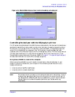
Instrument Control using the VXIplug&play Driver
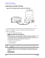
System Setup
1. Use an GPIB interconnect cable (such as 10833A/B/C/D) to connect the analyzer to the
GPIB interface card on your computer.
2. Switch on the computer.
3. Switch on the analyzer.
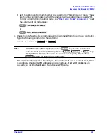
a. To verify the analyzer's address, press:
The analyzer has only one GPIB interface, though it occupies two addresses: one for
the instrument and one for the display. The display address is equal to the
instrument address with the least-significant bit incremented. The display address
is automatically set each time the instrument address is set.
The default analyzer addresses are:
— 16 for the instrument
— 17 for the display
CAUTION
Other devices connected to the bus cannot occupy the same address as the
analyzer or the display.
The analyzer should now be displaying the instrument's address in the upper right
section of the display. If the address is not 16, return the address to its default
setting (16) by pressing:
b. Set the system control mode to either “pass-control” or “talker/listener” mode. These
are the only control modes in which the analyzer will accept commands over GPIB.
For more information on control modes, see
“Bus Device Modes” on page 3-12
. To set
the system-control mode, press:
or
Local
SET ADDRESSES ADDRESS: 87xx
16
x1
Preset
Local
TALKER/LISTENER
Local
USE PASS CONTROL
Summary of Contents for 8719ES
Page 15: ...1 1 1 Alphabetical Command Reference ...
Page 293: ...2 1 2 Introduction to Instrument Control ...
Page 310: ...3 1 3 GPIB Programming ...
Page 334: ...4 1 4 Reading Analyzer Data ...
Page 343: ...5 1 5 Data Processing Chain ...
Page 350: ...6 1 6 Error Reporting ...
Page 364: ...7 1 7 Programming Examples ...
Page 502: ...A 1 A Preset Conditions ...
Page 517: ...B 1 B Command Listings ...


