


68
Agilent 86038B Photonic Dispersion and Loss Analyzer, Second Edition
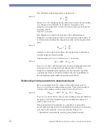
Relationship of setup parameters to ripple amplitude accuracy
Assuming a sufficiently small wavelength increment has been
chosen to reveal ripple across wavelength without aliasing, the
peak-to-peak amplitude of the ripple for insertion loss or group
delay will appear slightly less than the true amplitude.
One attenuation effect is caused by not sampling the
phenomena at its extremes. To reduce this effect, use a smaller
wavelength increment.
Another attenuation effect is caused when the two AM
sidebands produced by the RF modulation frequency stimulate
the DUT at different wavelengths, which occur at different
points with respect to the ripple phenomena.
This error in ripple amplitude depends on the period of the
ripple and the RF modulation frequency. Use smaller RF
modulation frequency to reduce this error.
Let us express the period of the ripple by its free spectral range
(FSR), which is the optical frequency change across one period
of the ripple. For example, ripple with a period of 80pm has a
FSR of about 10 GHz.
The case analyzed by
is when the sidebands lie equally
spaced on either side of a peak of a sinusoidal ripple shape. The
‘% of ps’ curve shows the percent error for GD ripple versus the
FSR of the ripple divided by the RF modulation frequency. For
small values of amplitude ripple, a similar curve applies. For
amplitude ripple of 6 dB peak-to-peak, use the
’% @ 6dB’ curve to determine the theoretical attenuation of the
ripple amplitude.
For example group delay ripple with 10 GHz FSR (80pm period),
when measured with a 500 MHz RF modulation frequency, will
appear to have a peak-to-peak amplitude with –5% error, or 95%
of the true amplitude.
If the RF modulation frequency is larger than one-fourth the
FSR, strange effects can appear. For example when (2 x
ModFreq)/(RippleFSR) = 0.5, 1.5, 2.5, and so on, the ripple may
appear to vanish. However, it is interesting to note the ripple
FSR will not be aliased to a false ripple rate in this condition
(provided the wavelength increment is less than half the ripple
period)
Summary of Contents for 86038B
Page 1: ...Agilent 86038B Photonic Dispersion and Loss Analyzer User s Guide ...
Page 4: ...4 ...
Page 20: ...20 Agilent 86038B Photonic Dispersion and Loss Analyzer Second Edition ...
Page 34: ...34 Agilent 86038B Photonic Dispersion and Loss Analyzer Second Edition Figure 2 b Rear Panel ...
Page 78: ...78 Agilent 86038B Photonic Dispersion and Loss Analyzer Second Edition ...
Page 92: ...92 Agilent 86038B Photonic Dispersion and Loss Analyzer Second Edition ...
Page 202: ...202 Agilent 86038B Photonic Dispersion and Loss Analyzer Second Edition End Sub ...
Page 348: ...348 Agilent 86038B Photonic Dispersion and Loss Analyzer Second Edition ...
Page 349: ......


