Getting Started
1
SCD and NCD User Manual
21
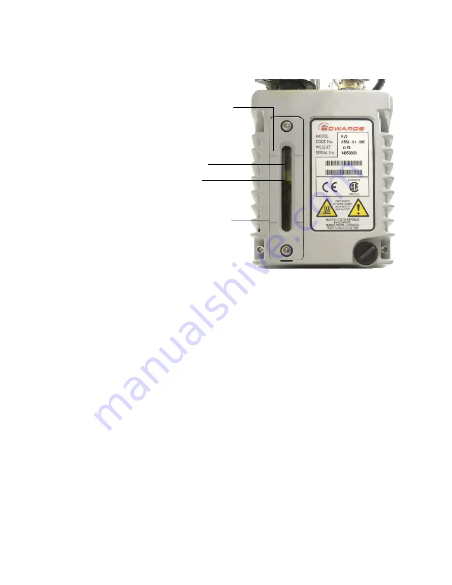
Figure 5
RV5 Vacuum pump oil sight gage
Oil level
Sight gage
Maximum oil level mark
Minimum oil level mark
Page 1: ...Agilent Technologies Agilent 8355 Sulfur and 8255 Nitrogen Chemiluminescence Detectors User Manual...
Page 2: ...not limited to the implied warranties of merchantability and fitness for a particular purpose Agilent shall not be liable for errors or for incidental or consequential damages in connection with the...
Page 3: ...ntroduction 24 Important Safety Information 25 Many internal parts of the detector carry dangerous voltages 25 Electrostatic discharge is a threat to GC electronics 26 Many parts are dangerously hot 2...
Page 4: ...Ozone destruction trap 42 Oil coalescing filter 42 FID adapter optional 42 NCD chiller 43 4 Operation Introduction 46 Integrated version 46 Setting Parameters 47 Parameters and ranges 47 Software cont...
Page 5: ...CD 73 Replace the Quartz Tube NCD 76 Check the Vacuum Pump Oil 80 Add Vacuum Pump Oil 81 Replace the Vacuum Pump Oil 83 Replace the Ozone Trap 85 Change the Oil Mist Filter 87 Clean the Detector Exter...
Page 6: ...g 102 Hydrogen Poisoning 103 Contaminated Gases 104 7 Performance Verification About Chromatographic Checkout 106 Prepare for Chromatographic Checkout 107 Prepare sample vials 108 Check SCD Performanc...
Page 7: ...ew of the 8355 SCD and 8255 NCD 18 Overview of Installation and First Startup 22 This chapter introduces the Agilent 8355 Sulfur Chemiluminescence Detector SCD and the Agilent 8255 Nitrogen Chemilumin...
Page 8: ...55 NCD Site Preparation Guide In addition Agilent provides other manuals familiarization information and help systems for self paced learning about the 7890B GC You will need to reference this general...
Page 9: ...en for English ch for jp for Version B 01 05 January 2013 2013 Agilent Technologies Inc All rights reserved Made in USA Agilent Technologies GC GCMS Hardware User Manuals and Videos S1N Disk 2 3 To in...
Page 10: ...needed for successful installation such as gases installation kits gas purifiers regulators tubing fittings consumable parts and so on At any time to refer to expected requirements for gas supplies r...
Page 11: ...information Instructions for using Early Maintenance Feedback EMF To look up a replacement part or consumable part Before performing any maintenance on the GC Troubleshooting Procedures for resolving...
Page 12: ...an Portuguese Russian Getting Started Print HTML PDF Safety Manual HTML PDF Installation and First Startup HTML PDF GC GC MS and ALS Site Prep Guide HTML PDF Maintaining Your GC HTML PDF Troubleshooti...
Page 13: ...m with detailed information common tasks and video tutorials on using the software Operation Manual HTML PDF Advanced Operation Manual HTML PDF Software Familiarization HTML Table 2 Languages availabl...
Page 14: ...In addition to the Hardware Manuals you will also find several User Apps on the Agilent GC and GC MS User Manuals Tools DVDs See below for a list of available Apps such as Parts Finder the GC Firmwar...
Page 15: ...RU PDQXDO RX FDQ TXLFNO FOLFN RQ SKRWRV DQG DUWZRUN WR LVRODWH WKH LQVWUXPHQW FRPSRQHQWV RI LQWHUHVW D VSHFL F W SH RI LQOHW RU GHWHFWRU LRQ VRXUFH RU VDPSOHU WUD IRU H DPSOH WKHQ YLVXDOO EURZVH WR W...
Page 16: ...ng Started Install the GC Firmware Update tool to install WKH ODWHVW UPZDUH RQWR your GC and sampler systems Install Method Developer Tools such as the Method Translator to help you convert a helium c...
Page 17: ...learning about all of the great features of your new system R1778A Agilent 7890 A B GC and OpenLAB ChemStation Operation R1914A Agilent 7890 A B GC Troubleshooting and Maintenance R2255A Agilent 7890...
Page 18: ...8255 NCD Figure 1 through Figure 5 show the controls parts and components of the 8355 SCD and 8255 NCD used or accessed during installation operation and maintenance Figure 1 Front view detector SCD...
Page 19: ...or back view Communications cable Burner heater connector Heater sensor connector Thermocouple connector Hydrogen gas input Oxidizer gas input Ozone gas input Vacuum connection Power connection Vacuum...
Page 20: ...as input Oxidizer gas input Ozone gas input Upper hydrogen output SCD only Oxidizer gas output Lower hydrogen output Pump oil pan 2LO PLVW OWHU DVVHPEO DQG OWHU 2LO UHWXUQ OLQH 2LO OO FDS 7UDS R RQH O...
Page 21: ...Getting Started 1 SCD and NCD User Manual 21 Figure 5 RV5 Vacuum pump oil sight gage Oil level Sight gage Maximum oil level mark Minimum oil level mark...
Page 22: ...the GC Cool the GC then turn off and unplug the power cord Remove covers 4 Prepare the detector mounting location 5 Unpack the vacuum pump Remove plugs Install oil coalescing filter and ballast 6 Ins...
Page 23: ...Symbols 29 Fuses 30 Safety and Regulatory Information 31 Intended Use 34 Cleaning 34 Recycling the Product 34 Technical Assistance 34 This chapter provides important safety and regulatory information...
Page 24: ...he Agilent 8255 NCD The SCD and NCD are typically installed onto the gas chromatograph GC by Agilent trained personnel If installing the SCD or NCD see the Installation Guide for instructions In addit...
Page 25: ...etector are connected to a power source even if the power switches are off potentially dangerous voltages exist on the Wiring between the detector power cord and the AC power supply AC power supply Wi...
Page 26: ...temperature before working on them If you must perform maintenance on hot parts use a wrench and wear thermally protective gloves Whenever possible cool the part of the instrument that you will be ma...
Page 27: ...r with an Agilent 7890B or 7890A GC the GC monitors any hydrogen gas streams If a stream shuts down because it is unable to reach its flow or pressure setpoint and if that stream is configured to use...
Page 28: ...igniter To avoid this hazard 1 Turn the automatic igniter off before you begin 2 Always measure gases separately WARNING Ozone is a hazardous gas and a strong oxidant Exposure to ozone should be minim...
Page 29: ...strument Agilent Technologies assumes no liability for the customer s failure to comply with these requirements See accompanying instructions for more information Indicates a hot surface Indicates haz...
Page 30: ...st fire hazard replace fuses only with fuses of the same type and rating WARNING Electrical shock hazard Disconnect the instrument from the mains supply before replacing fuses Table 3 AC board fuses F...
Page 31: ...y standards Canadian Standards Association CSA C22 2 No 61010 1 CSA Nationally Recognized Test Laboratory NRTL ANSI UL 61010 1 International Electrotechnical Commission IEC 61010 1 61010 2 010 EuroNor...
Page 32: ...d in a manner that protects human health and the environment For more information about where you can drop off your waste equipment for recycling please contact your local city recycling office or the...
Page 33: ...trical outlet so that the device and the radio or television are on separate electrical circuits 4 Make sure that all peripheral devices are also certified 5 Make sure that appropriate cables are used...
Page 34: ...s or use of the products in violation of applicable laws rules or regulations Cleaning To clean the unit disconnect the power and wipe down with a damp lint free cloth Recycling the Product For recycl...
Page 35: ...Agilent Technologies 3 System Description Specifications 36 Theory of Operation 37 Description of Major Components 39 This chapter provides typical performance specifications and describes the theory...
Page 36: ...tivity 2 x 10⁷ response S response C2 Precision and stability Typically based on one run per 30 minutes collected over 24 hours For example a 24 hour time span will contain approximately 48 replicate...
Page 37: ...emitted light is filtered and then is detected by a PMT The electrical signal produced is proportional to the amount of SO2 or NO2 formed in the reaction cell The sample exits the reaction cell passe...
Page 38: ...t of nitrogen in the sample The light h emitted by the chemical reaction is optically filtered and detected by a PMT A chiller cools the PMT to reduce thermal noise and help measure infrared light The...
Page 39: ...ner base region the column effluent mixes with the lower hydrogen flow and air at high temperature The resulting hydrogen flame combusts the effluent Low concentration components burn to form the usua...
Page 40: ...ulting hydrogen flame combusts the effluent Low concentration components will burn to form the usual combustion products including NO2 for compounds containing nitrogen The products are drawn upward t...
Page 41: ...erator The ozone generator provides ozone that reacts with any SO or NO in the reaction cell to generate SO2 and NO2 respectively These high energy species return to ground state by chemiluminescence...
Page 42: ...the reaction cell as well as transferring the ozone from the ozone generator into the reaction cell The vacuum pump also reduces non radiative collisional quenching of the emitting species in the rea...
Page 43: ...etector uses a Peltier cooler to lower the PMT temperature which in turn reduces noise This chiller cools the PMT relative to the current ambient temperature Higher laboratory ambient temperatures may...
Page 44: ...44 SCD and NCD User Manual 3 System Description...
Page 45: ...esource Conservation 55 Shutdown 56 Configure Auto Flow Zero on the GC 57 Configure the Detector 58 This chapter describes the how to use the 8355 SCD and 8255 NCD This chapter assumes familiarity wit...
Page 46: ...s use the integrated GC driver to access the operating parameters For standalone GC users access these parameters from the GC front panel and keyboard The settings and information provided by the driv...
Page 47: ...Method Base temperature 125 400 C 125 400 C 125 400 C Burner temperature 100 1000 C 100 1000 C 100 1000 C Chiller temperature NCD only On Off On Off On Off Lower hydrogen flow 5 25 mL min 1 25 mL min...
Page 48: ...session and edit the instrument acquisition parameters to change method settings Select the detector from the method editor typically Detectors Front Detector or Back Detector or Aux Detector as appro...
Page 49: ...e a front FID SCD the FID will be the front detector and the XCD will be an Aux detector To access configuration parameters using data system control select Configuration Modules See Figure 10 for an...
Page 50: ...n or off The PMT operates at a constant voltage 800 V Identifying the detector Table 5 lists the expected configurations for an XCD Table 5 Connections to the GC wiring harnesses XCD Installation Whic...
Page 51: ...the presence of active sites and other factors When starting an existing system typically wait at least 10 minutes before using the system to collect data A new burner or a new set of ceramic tubes m...
Page 52: ...zer gas flowing through the burner The firmware will not allow hydrogen to flow into the burner while there is no oxidizer to protect the system During startup and shutdown always turn on the pump fir...
Page 53: ...wer hydrogen flow to the oxygen supply Otherwise residual hydrogen in the tubing will continue diffuse into the burner and affect stability 1 Disconnect the Lower H2 line from the back of the detector...
Page 54: ...CD start the detector as follows 1 Access the method parameters At the GC front panel press Front Det Back Det or Aux Det In the data system select the detector in the method editor 2 Turn on the vacu...
Page 55: ...125 C to prevent condensation Maintain burner temperature of at least 200 C to prevent condensation Set an oven temperature of 30 C to minimize column bleed In addition a sleep method can also Turn on...
Page 56: ...off the base heater 8 Turn off the oxidizer flow 9 Turn off the vacuum pump 10 Turn off the detector power 11 If shutting down the GC turn off the GC Alternately create a method that turns off all det...
Page 57: ...duce drift See the GC Operation Manual for details 1 On the GC keypad press Options 2 Scroll to Calibration and press Enter 3 Scroll to select the appropriate detector front back aux 2 or aux 1 and pr...
Page 58: ...access the detector for example Config Front Det 2 Scroll to Oxidizer Gas and press Mode Type 3 Scroll to the correct gas type Air SCD or Oxygen NCD and press Enter If using data system control you ca...
Page 59: ...sable the PMT voltage 1 At the GC keyboard press the keys to access the detector for example press Config Front Det for an XCD mounted in the front position or press Config Back Det for an XCD mounted...
Page 60: ...60 SCD and NCD User Manual 4 Operation...
Page 61: ...of the NCD 68 Detector Maintenance Method 69 Attach a Column to the Detector 70 Replace the Inner Ceramic Tube SCD 73 Replace the Quartz Tube NCD 76 Check the Vacuum Pump Oil 80 Add Vacuum Pump Oil 81...
Page 62: ...cuum pump If not using the GC EMF feature manually keep a maintenance log that tracks Dates of maintenance and type of maintenance performed Operational changes that might impact performance such as c...
Page 63: ...dwards RV5 vacuum pump maintenance schedule Component Operating life The operating life is based on the total time logged during operation of the detector with the burner and the ozone generator On Ch...
Page 64: ...ity reflects the performance characteristics of a given system and decreased sensitivity may indicate the need for routine detector maintenance Sensitivity is typically reported as Calculate a minimum...
Page 65: ...installation tool G3488 81302 Sulfur chemiluminescence test sample Nitrogen chemiluminescence test sample Vacuum pump parts RV5 pump 230 V Inland G6600 64042 Pump tray RV5 pump G1946 00034 PM Kit RV5...
Page 66: ...tor 5020 8293 45 Ferrule graphite 0 8 mm id 0 45 mm capillary columns 500 2118 10 pk 32 Ferrule graphite 0 5 mm id 0 1 mm 0 2 mm 0 25 mm and 0 32 mm capillary columns 5080 8853 10 pk Column nut finger...
Page 67: ...XUQHU KHDWHU HWHFWRU EDVH QVXODWLRQ WRS QVXODWLRQ ERWWRP ROXPQ QXW HUUXOH FROXPQ QVXODWLRQ FXS LQFK JUDSKLWH IHUUXOH VWUDLJKW HW DVVHPEO DQG FRXSOLQJ 6KURXG DVVHPEO ROXPQ LQVWDOODWLRQ WRRO 2XWHU FHUD...
Page 68: ...ploded parts view Coupling 1 4 inch graphite ferrule straight Quartz tube Burner heater Detector base Insulation top Insulation bottom Column nut Ferrule Insulation cup 1 4 inch graphite ferrule strai...
Page 69: ...e generator 5 Leave on the vacuum pump 6 Keep helium carrier gas flowing 7 Set the oven to 30 C to minimize column bleed 8 Cool any other parts of the GC oven inlet and so forth as needed A maintenanc...
Page 70: ...directly to an XCD In a tandem FID XCD installation install the column into the FID as described in the FID instructions See the GC documentation WARNING The oven inlet or detector may be hot enough...
Page 71: ...pply gases c Turn off the ozone generator 3 Place a septum capillary column nut and ferrule on the column Figure 14 Place septum column nut and ferrule on the column 4 Insert the end of the column thr...
Page 72: ...he column 7 Snap off the column end The column may protrude about 1 mm beyond the end of the tool Inspect the end with a magnifying loupe to make certain that there are no burrs or jagged edges 8 Remo...
Page 73: ...s oven detectors valve box burner assembly and detector base cool to a safe handling temperature 40 C b Turn off all hydrogen flows Leave on the oxidizer and ozone supply gases c Turn off the ozone ge...
Page 74: ...ner ceramic tube 7 Place a new O ring over the end of the new inner ceramic tube and slide the O ring about 7 mm down the tube This dimension is not critical 8 Gently insert the tube and O ring assemb...
Page 75: ...line onto the outlet fitting Tighten until snug finger tight Do not overtighten 11 Restore the detector gas flows 12 Check for leaks at the upper hydrogen fitting Correct a leak as needed 13 Restore t...
Page 76: ...nce Method on page 69 Wait until the inlets oven detectors valve box burner assembly and detector base cool to a safe handling temperature 40 C b Turn off all hydrogen flows Leave on the oxidizer and...
Page 77: ...inch wrenches remove the outlet fitting from the nut on the top of the quartz tube 6 Gently slide the nut and its ferrule up and off of the quartz tube 7 Using 5 8 inch and 9 16 inch wrenches remove...
Page 78: ...about 1 cm This dimension is not critical The tube position will adjust as you tighten the lower nut onto the coupling 15 Carefully lower the burner assembly onto the detector base and thread the nut...
Page 79: ...Maintenance 5 SCD and NCD User Manual 79 19 Reinstall the protective shroud 20 Restore the detector operating conditions 21 Reset the EMF counter...
Page 80: ...ween the marks for Max and Min Figure 16 Checking the oil level 2 Check that the color of the pump oil is clear or almost clear with few suspended particles If the pump oil is dark or full of suspende...
Page 81: ...goggles Procedure 1 Shut down the detector and wait for the pump to turn off See Shutdown on page 56 2 Turn off the detector and unplug the pump power cord at the pump WARNING Never add pump oil while...
Page 82: ...evel window See Figure 16 on page 80 5 Reinstall the fill cap 6 Wipe off all excess oil around and underneath the pump 7 Reconnect the pump power cord 8 Turn on the detector and restore operating cond...
Page 83: ...laded large 8710 1029 Procedure 1 Shut down the detector and wait for the pump to turn off See Shutdown on page 56 2 Turn off the detector and unplug the pump power cord at the pump WARNING Never add...
Page 84: ...is near but not over the maximum mark beside the oil level window See Figure 16 on page 80 7 Reinstall the fill cap 8 Wipe off all excess oil around and underneath the pump 9 Reconnect the pump power...
Page 85: ...er gas flowing 2 Allow the vacuum pump to cool to a safe handling temperature 3 Remove the trap assembly and vacuum hose from the support bracket 4 Loosen the two hose clamps that secure the old ozone...
Page 86: ...86 SCD and NCD User Manual 5 Maintenance elbow must be nearest the pump intake If you removed the short connector hose from the pump intake reinstall it...
Page 87: ...il mist filter assembly with the 4 mm long handled hex wrench provided The smaller charcoal odor filter sits on top of the larger oil coalescing filter element While it is recommended to replace the o...
Page 88: ...pe dry with a clean soft cloth Do not allow cleaning fluids to drip into the detector or GC because liquids can damage the detector or GC electronics Do not use cleaning agents on the burner assembly...
Page 89: ...sors The 8355 SCD and 8255 NCD use electronic pressure control modules Typically set the 7890B GC to use automatic flow zeroing Calibration is generally not required However if needed the flow and pre...
Page 90: ...e The GC firmware controls the detector Any updates for the detector will be applied through the GC firmware See the GC Firmware Update Tool on the Agilent GC and GC MS User Manuals Tools DVDs or down...
Page 91: ...ms 92 Troubleshooting Table 93 Status Indicator LED 96 Detector Messages 97 Leaks 98 Power Problems 100 Ozone Generation Problems 101 Coking 102 Hydrogen Poisoning 103 Contaminated Gases 104 This chap...
Page 92: ...ther system failures for example a leak at the column inlet fitting Therefore the first step in troubleshooting is to isolate the problem to the GC inlet injector or column to the burner assembly or t...
Page 93: ...Replace the Quartz Tube NCD on page 76 Low Response Inappropriate hydrogen and oxidizer flow rates Check flow rates Adjust flow rates Leak in the detector Check for leaks in the detector and repair an...
Page 94: ...les Replace the ceramic tube See Replace the Inner Ceramic Tube SCD on page 73 or Replace the Quartz Tube NCD on page 76 Detector thermal shutdown Thermocouple open Contact Agilent for service Burner...
Page 95: ...Water in pump Cracked coalescing filter Milky yellow oil in the pump window Change coalescing filter and pump oil Reaction cell pressure high Ozone destruction trap clogged Remove ozone destruction tr...
Page 96: ...rator Note that the GC supplies power to the detector electronics independently of the power controlled by the switch on the front of the detector Yellow Indicates that the detector is not ready for o...
Page 97: ...Messages Check the GC status display for detector messages The GC will display and status and error messages that occur during operation as well as log detector maintenance and error messages in the...
Page 98: ...ner assembly See Checking for hydrogen and oxidizer leaks on WARNING Ozone is a hazardous gas and a strong oxidant Exposure to ozone should be minimized by using the instrument in a well ventilated ar...
Page 99: ...e 115 for NCD 3 Maintain these conditions for several minutes If the detector cannot maintain these flow rates contact Agilent for service 4 If the detector was able to maintain the flow rates turn of...
Page 100: ...NCD chiller vacuum pump and ozone generator comes from the detector mainframe and is controlled by the detector power switch No power If the detector does not appear to have power if the vacuum pump d...
Page 101: ...normally check that the inlet and ALS are operating normally and so on Troubleshoot ozone generation as follows 1 On the GC display note the detector output signal 2 Leave the vacuum pump on and ozone...
Page 102: ...itivity For example crude oils containing volatile metal complexes may contaminate the ceramic tubes In addition incomplete combustion of certain hydrocarbon containing compounds leaves behind coke de...
Page 103: ...the oxidizer flow this condition results in extremely reduced or no response If you suspect hydrogen poisoning Check for and resolve any flow shutdown Check for restrictions in the oxidizer supply lin...
Page 104: ...l performance Otherwise sulfur and other contaminants from gases may accumulate in the column and bleed out over time desensitizing the ceramic tubes and causing elevated baselines Moisture in the ozo...
Page 105: ...lent Technologies 7 Performance Verification About Chromatographic Checkout 106 Prepare for Chromatographic Checkout 107 Check SCD Performance 109 Check NCD Performance 114 This chapter describes how...
Page 106: ...mance can change The results presented here represent typical outputs for typical operating conditions and are not specifications The tests assume the following Use of an automatic liquid sampler If n...
Page 107: ...le parts are new and do not need replacement 1 Check the indicators dates on the gas supply traps Replace expended traps 2 Install new consumable parts for the inlet and prepare the correct injector s...
Page 108: ...mL ALS sample vial and cap the vial Syringe 5 L on column 5182 0836 0 32 mm needle for 5 L syringe 5182 0831 7693A ALS Needle support insert COC G4513 40529 7683B ALS Needle support assembly for 0 25...
Page 109: ...oaded in sample turret 4 mL solvent vial with diffusion cap filled with isooctane and inserted in Solvent A injector position 4 mL solvent vial with diffusion cap filled with isooctane and inserted in...
Page 110: ...listed in Table 14 Table 14 SCD Checkout conditions Column and sample Type DB 1 30 m 0 32 mm 1 m 123 1033 Sample SCD checkout 5190 7003 Column flow 3 5 mL min helium Column mode Constant flow Split sp...
Page 111: ...makeup flow 20 mL min SCD oxidizer flow 0 SCD upper H2 flow 40 mL min Lower H2 flow Not applicable for FID SCD Oven Initial temp 50 C Initial time 3 0 min Rate 1 25 C min Ramp 1 temp 160 C Ramp 1 hold...
Page 112: ...em a Press Prep Run to prepare the inlet for splitless injection b When the GC becomes ready inject 1 L of the checkout sample and press Start on the GC Solvent B post washes 3 Solvent B wash volume 8...
Page 113: ...nstalled Note that the response for a tandem FID SCD installation will be approximately 1 10 of the response shown in this example due to the reduced amount of sample that reaches the SCD min 2 5 5 7...
Page 114: ...one supply gas moisture trap and other traps are in date Empty waste vials loaded in sample turret 4 mL solvent vial with diffusion cap filled with isooctane and inserted in Solvent A injector positio...
Page 115: ...ntinue before the baseline becomes completely stable 6 Create or load a method with the parameter values listed in Table 15 Table 15 NCD Checkout conditions Column and sample Type HP 5 30 m 0 32 mm 0...
Page 116: ...time 3 0 min Rate 1 25 C min Ramp 1 temp 250 C Ramp 1 hold time 2 min Post run temp 50 C ALS settings if installed Sample washes 2 Sample pumps 6 Sample wash volume 8 L maximum Injection volume 1 L Sy...
Page 117: ...GC If performing a manual injection with or without a data system a Press Prep Run to prepare the inlet for splitless injection b When the GC becomes ready inject 1 L of the checkout sample and press...
Page 118: ...The following chromatogram shows typical results for a new detector with new consumable parts installed min 0 2 4 6 8 10 0 1000 2000 3000 4000 NCD1 A Front Signal C CHEM32 2 DATA XCD DATA FEB2015 NCD...