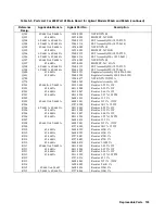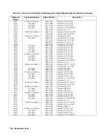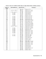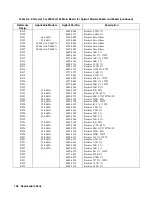
Replaceable Parts 117
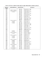
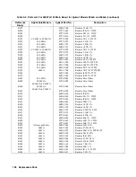
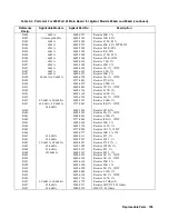
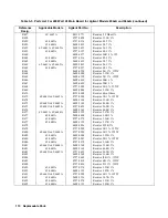
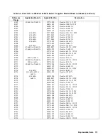
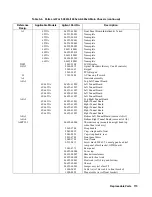
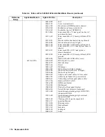
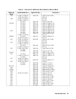
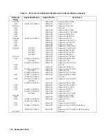
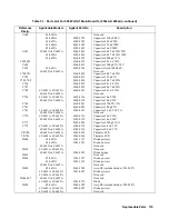
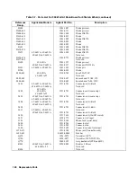
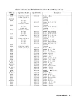
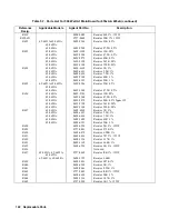
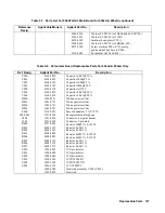
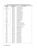
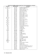
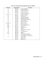
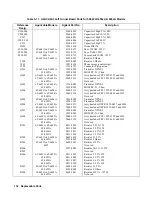
Table 5-7. Parts List For 500 Watt A1 Main Board for 655xA & 665xA
Reference
Desig.
Applicable Models
Agilent Part No.
Description
C403
65/6651A, 65/6652A
0160-5422
Capacitor .047 uF 20%
65/6653A-65/6655A
Not used
C404
65/6651A, 65/6652A
Not used
65/6654A, 65/6655A
Not used
65/6653A
0160-6803
Capacitor .047 250V
C405,406
65/6651A
0180-4321
Capacitor 39000 uF 25V
65/6652A
0160-4264
Capacitor 18000 uF 50V
65/6653A
0180-4272
Capacitor 10000 uF 80V
65/6654A
0180-4263
Capacitor 4000 uF 125V
65/6655A
0180-4311
Capacitor 1200 uF 250V
C407
65/6651A
0180-4321
Capacitor 39000 uF 25V
65/6652A
0160-4264
Capacitor 18000 uF 50V
65/6653A
0180-4272
Capacitor l0000 uF 80V
65/6654A, 65/6655A
Not used
C408,409
65/6651A
0180-4321
Capacitor 39000 uF 25V
65/6652A-65/6655A
Not used
C411
65/6651A, 65/6652A
0160-5422
Capacitor .047 uF 20%
65/6653A-65/6655A
Not used
C412
65/6651A, 65/6652A
Not used
65/6654A, 65/6655A
Not used
65/6653A
0160-6803
Capacitor .047 uF 250V
65/6652A, 65/6654A
Not used
C413
65/6651A-65/6653A,
65/6655A
0160-5469
Capacitor luF l0% 50V
65/6654A
0160-5101
Capacitor 1 uF 10%
C414,415
0160-5422
Capacitor .047 uF 20%
C416
65/6651A
0180-4321
Capacitor 39000 uF 25V
65/6652A, 65/6653A
0180-3963
Capacitor 17000 uF 16V
65/6654A
Not used
C417
65/6651A-65/6653A
Not Used
65/6654A, 65/6655A
0180-3497
Capacitor 6800 uF 16V
C418
65/6651A-65/6653A
Not Used
65/6654A
0160-0168
Capacitor .1 uF 10%
65/6655A
0160-4065
Capacitor .1 uF 10%
C450, 451
0160-4281
Capacitor 2200 pF 20%
C452
0160-4962
Capacitor 1.0 uF 20%
C501
0160-5422
Capacitor .047 uF 20%
C502,503
0160-4805
Capacitor 47 pF 5% l00V
C504
0160-5422
Capacitor .047 uF 20%
C505
65/6651A-65/6655A
0160-4129
Capacitor 1 uF 35V
C506
0160-4801
Capacitor 100 pF 5%
C507
0160-5422
Capacitor .047 uF 20%
C509
0160-5422
Capacitor .047 uF 20%
C510
0160-4801
Capacitor 100 pF 5%
C512
0160-5422
Capacitor .047 uF 20%
C513
0160-4801
Capacitor l00 pF 5%
C515
0160-5422
Capacitor .047 uF 20%
C516
0160-480l
Capacitor 100 pF 5%
Summary of Contents for 6541A
Page 12: ...12 Verification Figure 2 1 Basic Test Setup CV TESTS CV TESTS ...
Page 18: ...18 Verification Figure 2 3 CC RMS Noise Measurement Test Setup ...
Page 30: ......
Page 32: ...32 Troubleshooting Figure 3 1 Top View with Cover Removed for 655xA 665xA Models Sheet 1 of 2 ...
Page 33: ...Troubleshooting 33 Figure 3 1 Top View with Cover Removed for 655xA 665xA Models Sheet 2 of 2 ...
Page 37: ...Troubleshooting 37 Figure 3 2 Overall Troubleshooting Flow Diagram Sheet 1 of 4 ...
Page 38: ...38 Troubleshooting Figure 3 2 Overall Troubleshooting Flow Diagram Sheet 2 of 4 ...
Page 39: ...Troubleshooting 39 Figure 3 2 Overall Troubleshooting Flow Diagram Sheet 3 of 4 ...
Page 40: ...40 Troubleshooting Figure 3 2 Overall Troubleshooting Flow Diagram Sheet 4 of 4 ...
Page 51: ...Troubleshooting 51 Figure 3 5 No Display Troubleshooting ...
Page 52: ...52 Troubleshooting Figure 3 6 OV Will Not Fire Troubleshooting ...
Page 53: ...Troubleshooting 53 Figure 3 7 OV At Turn On Troubleshooting Sheet 1 of 2 ...
Page 54: ...54 Troubleshooting Figure 3 7 OV At Turn On Troubleshooting Sheet 2 of 2 ...
Page 55: ...Troubleshooting 55 Figure 3 8 Output Held Low Troubleshooting Sheet 1 of 2 ...
Page 56: ...56 Troubleshooting Figure 3 8 Output Held Low Troubleshooting Sheet 2 of 2 ...
Page 57: ...Troubleshooting 57 Figure 3 9 Output Held High Troubleshooting ...
Page 58: ...58 Troubleshooting Figure 3 10 DAC Circuits Troubleshooting ...
Page 60: ...60 Troubleshooting Figure 3 13 Serial Down Troubleshooting Sheet 1 of 2 ...
Page 61: ...Troubleshooting 61 Figure 3 13 Serial Down Troubleshooting Sheet 2 of 2 ...
Page 62: ...62 Troubleshooting Figure 3 14 Secondary Down Troubleshooting Sheet 1 of 2 ...
Page 63: ...Troubleshooting 63 Figure 3 14 Secondary Down Troubleshooting Sheet 2 of 2 ...
Page 64: ...64 Troubleshooting Figure 3 15 Slow Down Programming Troubleshooting ...
Page 65: ...Troubleshooting 65 Figure 3 16 Isolator Board Circuits Troubleshooting ...
Page 80: ......
Page 87: ...Principles of Operation 87 Figure 4 4 Output Power and Control Circuits ...
Page 94: ......
Page 136: ......
Page 145: ...Figure 6 1 Power Supply Interconnection Diagram for All Models ...
Page 146: ...Figure 6 2 AC Power Distribution Diagram for 655xA 665xA Models ...
Page 147: ...Figure 6 3 GPIB Board Assembly Diagram sheet 1 of 2 ...
Page 148: ...2 3 4 1 6 5 7 8 Figure 6 3 GPIB Board Schematic Diagram sheet 2 of 2 ...
Page 149: ...Figure 6 4 Front Panel Board Assembly Diagram sheet 1 of 2 ...
Page 150: ...Figure 6 4 Front Panel Board Schematic Diagram sheet 2 of 2 ...
Page 152: ...Figure 6 5 A1 Main Board Assembly Diagram for 654xA 664xA Models Only ...
Page 160: ...Figure 6 6 Left Tunnel Circuits Schematic Diagram for 654xA 664xA Models Only sheet 2 ...
Page 162: ...Figure 6 7 Right Tunnel Circuits Schematic Diagram for 654xA 664xA Models Only sheet 2 ...
Page 164: ......
Page 168: ......

