Troubleshooting 71
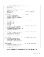
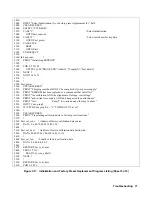
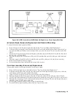
Figure 3-17. Initialization and Factory Preset Replacement Program Listing (Sheet 5 of 6)
2030
!
2040
INPUT "Select Initialization (I) or Factory preset replacement (F).",Sel$
2050
CLEAR SCREEN
2060
SELECT (UPC$(Sel$))
2070
CASE "I"
! Select Initialization
2080
GOTO Init_eeprom
2090
CASE "F"
! Select install new factory data
2100
GOTO Fact_preset
2110
CASE ELSE
2120
BEEP
2130
GOTO Start
2140
END SELECT
2150
!
2160 Init_eeprom: !
2170
PRINT "Initializing EEPROM"
2180
!
2190
FOR I=1 TO 45
2200
OUTPUT @Ps;"DIAG:EEPR '';Addr(I);'','';Length(I);'','';Init_data(I)
2210
NEXT I
2220
GOTO Cal_off
2230
!
2240
!
2250 Fact_preset: !
2260
CLEAR SCREEN
2270
PRINT "This program should ONLY be completed if your power supply"
2280
PRINT "EEPROM has been replaced or a component that will effect"
2290
PRINT "the calibration AND the alignment of voltage, overvoltage"
2300
PRINT "and current is complete AND unit has passed the performance"
2310
PRINT "test. Enter C to continue, any other key to abort."
2320
INPUT Cont_prog$
2330 IF (UPC$(Cont_prog$))< >"C" THEN GOTO Cal_off
2340
!
2350
CLEAR SCREEN
2360 PRINT "Transferring calibration data to factory preset locations."
2370
!
2380 Fact_cal_sour: ! Address of factory calibration data source
2390 DATA 2,6,68,72,20,24,76,80,150
2400
!
2410 Fact_cal_dest: ! Address of factory calibration data destination
2420 DATA 84,88,92,96,100,104,108,112,116
2430
!
2440 Fact_cal_len: ! Length of factory calibration data
2450
DATA 4,4,4,4,4,4,4,4,2
2460
!
2470
RESTORE Fact_cal_sour
2480
F0R I=1 TO 9
2490
READ Cal_sour_addr(I)
2500
NEXT I
2510
!
2520
RESTORE Fact_cal_dest
2530
FOR I=1 T0 9
Summary of Contents for 6541A
Page 12: ...12 Verification Figure 2 1 Basic Test Setup CV TESTS CV TESTS ...
Page 18: ...18 Verification Figure 2 3 CC RMS Noise Measurement Test Setup ...
Page 30: ......
Page 32: ...32 Troubleshooting Figure 3 1 Top View with Cover Removed for 655xA 665xA Models Sheet 1 of 2 ...
Page 33: ...Troubleshooting 33 Figure 3 1 Top View with Cover Removed for 655xA 665xA Models Sheet 2 of 2 ...
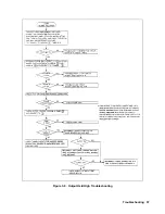
Page 37: ...Troubleshooting 37 Figure 3 2 Overall Troubleshooting Flow Diagram Sheet 1 of 4 ...
Page 38: ...38 Troubleshooting Figure 3 2 Overall Troubleshooting Flow Diagram Sheet 2 of 4 ...
Page 39: ...Troubleshooting 39 Figure 3 2 Overall Troubleshooting Flow Diagram Sheet 3 of 4 ...
Page 40: ...40 Troubleshooting Figure 3 2 Overall Troubleshooting Flow Diagram Sheet 4 of 4 ...
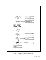
Page 51: ...Troubleshooting 51 Figure 3 5 No Display Troubleshooting ...
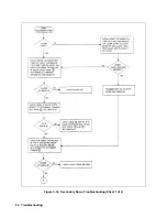
Page 52: ...52 Troubleshooting Figure 3 6 OV Will Not Fire Troubleshooting ...
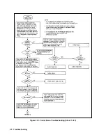
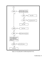
Page 53: ...Troubleshooting 53 Figure 3 7 OV At Turn On Troubleshooting Sheet 1 of 2 ...
Page 54: ...54 Troubleshooting Figure 3 7 OV At Turn On Troubleshooting Sheet 2 of 2 ...
Page 55: ...Troubleshooting 55 Figure 3 8 Output Held Low Troubleshooting Sheet 1 of 2 ...
Page 56: ...56 Troubleshooting Figure 3 8 Output Held Low Troubleshooting Sheet 2 of 2 ...
Page 57: ...Troubleshooting 57 Figure 3 9 Output Held High Troubleshooting ...
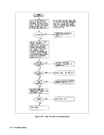
Page 58: ...58 Troubleshooting Figure 3 10 DAC Circuits Troubleshooting ...
Page 60: ...60 Troubleshooting Figure 3 13 Serial Down Troubleshooting Sheet 1 of 2 ...
Page 61: ...Troubleshooting 61 Figure 3 13 Serial Down Troubleshooting Sheet 2 of 2 ...
Page 62: ...62 Troubleshooting Figure 3 14 Secondary Down Troubleshooting Sheet 1 of 2 ...
Page 63: ...Troubleshooting 63 Figure 3 14 Secondary Down Troubleshooting Sheet 2 of 2 ...
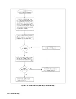
Page 64: ...64 Troubleshooting Figure 3 15 Slow Down Programming Troubleshooting ...
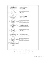
Page 65: ...Troubleshooting 65 Figure 3 16 Isolator Board Circuits Troubleshooting ...
Page 80: ......
Page 87: ...Principles of Operation 87 Figure 4 4 Output Power and Control Circuits ...
Page 94: ......
Page 136: ......
Page 145: ...Figure 6 1 Power Supply Interconnection Diagram for All Models ...
Page 146: ...Figure 6 2 AC Power Distribution Diagram for 655xA 665xA Models ...
Page 147: ...Figure 6 3 GPIB Board Assembly Diagram sheet 1 of 2 ...
Page 148: ...2 3 4 1 6 5 7 8 Figure 6 3 GPIB Board Schematic Diagram sheet 2 of 2 ...
Page 149: ...Figure 6 4 Front Panel Board Assembly Diagram sheet 1 of 2 ...
Page 150: ...Figure 6 4 Front Panel Board Schematic Diagram sheet 2 of 2 ...
Page 152: ...Figure 6 5 A1 Main Board Assembly Diagram for 654xA 664xA Models Only ...
Page 160: ...Figure 6 6 Left Tunnel Circuits Schematic Diagram for 654xA 664xA Models Only sheet 2 ...
Page 162: ...Figure 6 7 Right Tunnel Circuits Schematic Diagram for 654xA 664xA Models Only sheet 2 ...
Page 164: ......
Page 168: ......

