70 Troubleshooting
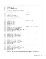
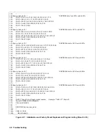
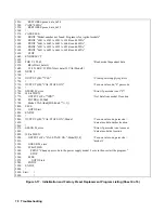
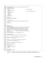
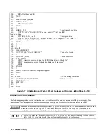
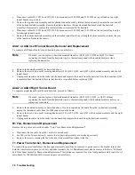
Figure 3-17. Initialization and Factory Preset Replacement Program Listing (Sheet 4 of 6)
1530
RESTORE Eprom_data_6x54
1540
CASE "6655A"
1550
RESTORE Eprom_data_6x55
1560
!
1570
CASE ELSE
1580
PRINT "Model number not found. Program is for Agilent models"
1590
PRINT "6541A, 6542A, 6543A, 6544A and 6545A"
1600
PRINT "6641A, 6642A, 6643A, 6644A and 6645A"
1610
PRINT "6551A, 6552A, 6553A, 6554A and 6555A"
1620
PRINT "6651A, 6652A, 6663A, 6654A and 6655A"
1630
STOP
1640
END SELECT
1650
!
1660
FOR I=1 T0 45
! Read model dependent data
1670
READ Init_data(I)
1680
IF I=21 0R I=32 THEN Init_data(I)=VAL(Model$)
1690
NEXT I
1700
!
1710
OUTPUT @Ps;"*CLS"
! Clears power supply registers
1720
!
1730
OUTPUT @Ps;"CAL;STATE ON,"
! Turn on cal mode, "0" passcode
1740
!
1750
G0SUB Ps_error
! Error if passcode is not "0"!
1760
IF Err THEN
1770
OUTPUT @Ps;"*IDN?"
! Get data from model # location
1780
ENTER @Ps;Idn$
1790
Model=VAL(Idn$[POS(Idn$,",")+1] )
1800
ELSE
1810
GOTO Start
1820
END IF
1830
!
1840
OUTPUT @Ps;"CAL:STATE ON,";Model
! Turn on cal mode, passcode =
1850
! data at model number location
1860
!
1870
G0SUB Ps_error
! Error if passcode is not same as
1880
! data at model & location
1890
IF Err THEN
1900
OUTPUT @Ps;"CAL:STATE ON,";Model$[1,4]
! Turn on cal mode, passcode =
1910
! model #
1920
GOSUB Ps_error
1930
IF Err THEN
1940
PRINT "Change pass code to the power supply model # or zero then restart the program."
1950
STOP
1960
ELSE
1970
GOTO Start
1980
END IF
1990
END IF
2000
!
2010 Start: !
2020
!
Summary of Contents for 6541A
Page 12: ...12 Verification Figure 2 1 Basic Test Setup CV TESTS CV TESTS ...
Page 18: ...18 Verification Figure 2 3 CC RMS Noise Measurement Test Setup ...
Page 30: ......
Page 32: ...32 Troubleshooting Figure 3 1 Top View with Cover Removed for 655xA 665xA Models Sheet 1 of 2 ...
Page 33: ...Troubleshooting 33 Figure 3 1 Top View with Cover Removed for 655xA 665xA Models Sheet 2 of 2 ...
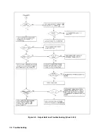
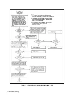
Page 37: ...Troubleshooting 37 Figure 3 2 Overall Troubleshooting Flow Diagram Sheet 1 of 4 ...
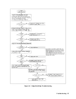
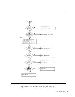
Page 38: ...38 Troubleshooting Figure 3 2 Overall Troubleshooting Flow Diagram Sheet 2 of 4 ...
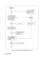
Page 39: ...Troubleshooting 39 Figure 3 2 Overall Troubleshooting Flow Diagram Sheet 3 of 4 ...
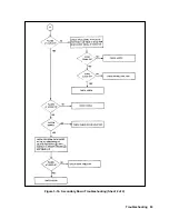
Page 40: ...40 Troubleshooting Figure 3 2 Overall Troubleshooting Flow Diagram Sheet 4 of 4 ...
Page 51: ...Troubleshooting 51 Figure 3 5 No Display Troubleshooting ...
Page 52: ...52 Troubleshooting Figure 3 6 OV Will Not Fire Troubleshooting ...
Page 53: ...Troubleshooting 53 Figure 3 7 OV At Turn On Troubleshooting Sheet 1 of 2 ...
Page 54: ...54 Troubleshooting Figure 3 7 OV At Turn On Troubleshooting Sheet 2 of 2 ...
Page 55: ...Troubleshooting 55 Figure 3 8 Output Held Low Troubleshooting Sheet 1 of 2 ...
Page 56: ...56 Troubleshooting Figure 3 8 Output Held Low Troubleshooting Sheet 2 of 2 ...
Page 57: ...Troubleshooting 57 Figure 3 9 Output Held High Troubleshooting ...
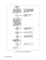
Page 58: ...58 Troubleshooting Figure 3 10 DAC Circuits Troubleshooting ...
Page 60: ...60 Troubleshooting Figure 3 13 Serial Down Troubleshooting Sheet 1 of 2 ...
Page 61: ...Troubleshooting 61 Figure 3 13 Serial Down Troubleshooting Sheet 2 of 2 ...
Page 62: ...62 Troubleshooting Figure 3 14 Secondary Down Troubleshooting Sheet 1 of 2 ...
Page 63: ...Troubleshooting 63 Figure 3 14 Secondary Down Troubleshooting Sheet 2 of 2 ...
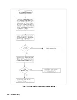
Page 64: ...64 Troubleshooting Figure 3 15 Slow Down Programming Troubleshooting ...
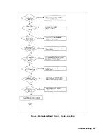
Page 65: ...Troubleshooting 65 Figure 3 16 Isolator Board Circuits Troubleshooting ...
Page 80: ......
Page 87: ...Principles of Operation 87 Figure 4 4 Output Power and Control Circuits ...
Page 94: ......
Page 136: ......
Page 145: ...Figure 6 1 Power Supply Interconnection Diagram for All Models ...
Page 146: ...Figure 6 2 AC Power Distribution Diagram for 655xA 665xA Models ...
Page 147: ...Figure 6 3 GPIB Board Assembly Diagram sheet 1 of 2 ...
Page 148: ...2 3 4 1 6 5 7 8 Figure 6 3 GPIB Board Schematic Diagram sheet 2 of 2 ...
Page 149: ...Figure 6 4 Front Panel Board Assembly Diagram sheet 1 of 2 ...
Page 150: ...Figure 6 4 Front Panel Board Schematic Diagram sheet 2 of 2 ...
Page 152: ...Figure 6 5 A1 Main Board Assembly Diagram for 654xA 664xA Models Only ...
Page 160: ...Figure 6 6 Left Tunnel Circuits Schematic Diagram for 654xA 664xA Models Only sheet 2 ...
Page 162: ...Figure 6 7 Right Tunnel Circuits Schematic Diagram for 654xA 664xA Models Only sheet 2 ...
Page 164: ......
Page 168: ......

