background image

38

34405A User’s and Service Guide

2

Features and Functions

Reading Error Messages 

The following procedure shows you to read error messages from the front 
panel. For remote operation, refer to the SYSTem:ERRor? command in the 

Agilent 34405A Online Programmer’s Reference

 online help. 

1

To access the Utility Menu, press 

2

Press 

seven times until 

Error

 is shown in the primary display. 

3

If there are no errors in the error queue, the secondary display shows 

nonE

If there are one or more errors, 

Error

 is shown in the primary display 

and 

nn

.Err

 is shown flashing in the secondary display (where 

nn

 is the 

total number of errors in the error queue). For example, if there are 
three errors in the queue,

 03.Err

 will flash in the secondary display. 

Errors are numbered and stored in the queue in the order they 
occurred.

4

If there are errors in the error queue, press

to read the first 

error. The error number in the queue is shown in the primary display 
and the actual error number is shown in the secondary display. 

5

Repeat step 4 for all errors in the error queue

(you can also use 

 to view the previous error). 

6

After reading all errors, 

press 

twice to exit the Utility Menu. 

7

The error queue is automatically cleared after 

 has been pressed 

and the utility menu is exited.

Shift

Utility

Store

Recall

Store

Recall

Store

Recall

Store

Recall

Edit

Store

Recall

Store

Recall

Edit

Downloaded from 

www.Manualslib.com


manuals search engine


Summary of Contents for 34405A

Page 1: ...Agilent Technologies Agilent 34405A 5 Digit Multimeter User s and Service Guide Downloaded from www Manualslib com manuals search engine...

Page 2: ...ed herein Should Agilent and the user have a separate written agreement with warranty terms covering the material in this document that conflict with these terms the warranty terms in the sep arate ag...

Page 3: ...nued protection against fire replace the line fuse and the current protection fuse only with fuses of the specified type and rating WARNING IEC Measurement Category II The HI and LO input terminals ma...

Page 4: ...rms maximum current flowing from the LO input terminal This is Protection Limit D in the figure Note that the current input terminal will be at approximately the same voltage as the LO terminal Note T...

Page 5: ...for more information The Agilent 34405A is provided with an Agi lent 34138A Test Lead Set described below Test Lead Ratings Test Leads 1000V 15A Fine Tip Probe Attachments 300V 3A Mini Grabber Attachm...

Page 6: ...trument is available on the Web site You can search the DoC by its product model or description http regulations corporate agilent com DoC search htm NOTE If you are unable to search for the respectiv...

Page 7: ...g and Connecting the USB Interface 18 SCPI Commands 18 Making Measurements 20 Measuring AC or DC Voltage 20 Measuring Resistance 21 Measuring AC RMS or DC Current up to 1 2A 21 Measuring AC RMS or DC...

Page 8: ...On State 43 Triggering the Multimeter 45 3 Measurement Tutorial 47 DC Measurement Considerations 48 Noise Rejection 49 Resistance Measurement Considerations 51 AC Measurements 52 True RMS AC Measureme...

Page 9: ...s 86 Adjustments 88 Zero Adjustment 88 Gain Adjustments 89 DC Voltage Gain Adjustment Procedure 91 DC Current Gain Adjustment Procedure 92 AC Voltage Gain Adjustment Procedure 94 AC Current Gain Adjus...

Page 10: ...Specifications 1 126 Temperature and Capacitance Specifications 1 127 Operating Specifications 128 Supplemental Measurement Specifications 129 General Characteristics 133 To Calculate Total Measureme...

Page 11: ...e Rear Panel at a Glance 17 Measuring AC or DC Voltage 20 Measuring Resistance 21 Measuring AC RMS or DC Current up to 1 2A 21 Measuring AC RMS or DC Current up to 12A 22 Measuring Frequency 22 Testin...

Page 12: ...l display measurements Ten measurement functions AC voltage DC voltage Two wire resistance AC current DC current Frequency Continuity Diode Test Temperature Capacitance Six math functions Null dBm dB...

Page 13: ...ower switch to turn on the multimeter The front panel display illuminates while the multimeter performs its power on self test If the multimeter does not power on refer Operating Checklist on page 106...

Page 14: ...tarted Tutorial Adjusting the Handle To adjust the handle grasp the handle by the sides and pull outward Then rotate the handle to the desired position Benchtop Positions Carrying Position Downloaded...

Page 15: ...405A 5 Digit Multimeter mV DC 4 5 ACI DCI DCV ACV Store Recall MnMx Temp Limit Null Freq 12A Fused 1 2 3 5 6 7 8 9 4 Edit Enter mV DC Range 1 Display 2 On Off Switch 3 Measurement Function and Resolut...

Page 16: ...nction and Units mVA DC AC Mk Hz nF C F dBm Remote ManRng Hold Limit Null MnMx mVA DC AC Mk Hz nF C F dBm MaxMinAvgN Ref R Value Store Recall HiLo Limit Range CAL Shift 5 6 7 1 2 3 4 System Annunciato...

Page 17: ...ce Guide 17 The Rear Panel at a Glance 4 AC Power Connector 5 AC Line Voltage Selector 6 AC Line Fuse 1 USB Interface Connector 2 Model and Serial Number Label 3 Chassis Ground Lug 1 3 4 2 5 6 Downloa...

Page 18: ...plies with the syntax rules and conventions of SCPI Standard Commands for Programmable Instruments Local Shift NOTE To easily configure and verify an interface connection between the 34405A and your P...

Page 19: ...y sending the SYSTem VERSion command from the remote interface You can query the SCPI version from the remote interface only The SCPI version is returned in the form YYYY V where YYYY represents the y...

Page 20: ...ed true rms measures the AC component with up to 400 VDC bias on any range Crest Factor Maximum 5 1 at full scale Input Impedance 1 M 2 in parallel with 100pF on all ranges Input Protection 750V rms o...

Page 21: ...C Current Ranges 10 0000 mA 100 000 mA 1 00000 A Shunt Resistance 0 1 to 10 for 10mA to 1A ranges Input Protection Front Panel 1 25A 500V FH fuse for I terminal Typical Display 12A rms 1000VDC 500Vpk...

Page 22: ...counting technique Signal level 10 of range to full scale input on all ranges Gate Time 0 1 second or 1 period of the input signal whichever is longer Input Protection 750V rms on all ranges HI termi...

Page 23: ...V open circuit voltage Response Time 70 samples second with audible tone Input Protection 1000 V HI terminal Shift Cont Open Circuit Display 12A rms 1000VDC 500Vpk 1 2A rms 1 25A 500V FH LO CAT II 30...

Page 24: ...C 110 0 F to 300 0 F Auto ranging measurement no manual range selection Measurement Method 2 wire Ohms measurement of 5 k thermistor sensor E2308A with computed conversion Input Protection 1000 V HI...

Page 25: ...on the selected range the multimeter provides these overload indications OL from the front panel or 9 9E 37 from the remote interface For frequency measurements ranging applies to the signal s input v...

Page 26: ...racy and noise rejection 4 digit readings provide for faster readings The continuity and diode test functions have a fixed 4 digit display Capacitance and temperature have a fixed 3 digit display For...

Page 27: ...Values in the Secondary Display 40 Storing and Recalling Instrument States 41 Reset Power On State 43 Triggering the Multimeter 45 This chapter contains detailed information on the multimeter and how...

Page 28: ...operation and then turns on the second math operation All math operations are automatically turned off when changing measuring functions Range changing is allowed for all math operations For remote o...

Page 29: ...C Volts AC Volts DC Current AC Current Resistance Frequency Capacitance and Temperature dBm The logarithmic dBm decibels relative to one milliwatt scale is often used in RF signal measurements The mul...

Page 30: ...the range of 120 000 dBm with 0 001 dBm resolution shown Min Max The Min Max Minimum Maximum operation stores the minimum and maximum values the average and the number of readings during a series of m...

Page 31: ...HI when the reading is outside the high limit and LO when the reading is outside the low limit When the beeper is ON see Using the Utility Menu on page 36 the beeper beeps on the transition from PASS...

Page 32: ...ted right of the primary display see The Display at a Glance on page 16 The Math Value Annunciators are located under the secondary display and assist in viewing and editing math values in the seconda...

Page 33: ...he secondary display allows you to show the measurement range for most measurement functions or to select a predefined secondary measurement function For example a typical primary display showing DCV...

Page 34: ...condary display for measurements All math operations offer predefined displays that can be presented on the secondary display as described on the next page For remote operation refer to the DISPlay WI...

Page 35: ...ices for the present math operation as shown in the table below Reading is used in the table below to indicate the original measured reading value mV DC Limit Disp Secondary Display Math Operation Pri...

Page 36: ...ns SYSTem BEEPer STATe mode P On rESEt LASt Enable or disable power on recall of State 0 last power off instrument state Note The multimeter always saves the power down state This just determines whet...

Page 37: ...he setting you want 4 When the correct setting is displayed in the secondary display press to save the setting and advance to the next item 5 Repeat steps 4 and 5 for all items in the Utility Menu 6 W...

Page 38: ...er of errors in the error queue For example if there are three errors in the queue 03 Err will flash in the secondary display Errors are numbered and stored in the queue in the order they occurred 4 I...

Page 39: ...the beep state turned OFF in the following cases A continuity measurement is less than or equal to the continuity threshold A SYSTem BEEPer command is sent An error is generated In addition to the bee...

Page 40: ...electing the Value to Edit With the math function enabled press until the Ref Value Ref R Value Hi Limit or Lo Limit you want to edit is displayed in the secondary display To select the editing mode p...

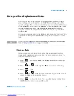
Page 41: ...e Programmer s Reference online help Storing a State Before storing an instrument state select the measurement function range math operations and so on that you want saved as a state To store the inst...

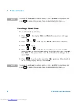
Page 42: ...calling a state select ESC 5 Press to perform the recall or ESC operation When finished the secondary display briefly shows donE NOTE To escape the recall operation without recalling a state select ES...

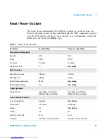
Page 43: ...AUTO AUTO Resolution 5 digits 5 digits Temperature Units C User setting Math Operations Math State Function Off Null Off Null Math Registers Cleared Cleared dBm Reference Resistance 600 User setting...

Page 44: ...us Registers Masks Transition Filters Cleared Cleared if power on status clear enabled no change otherwise Serial Number Unique value per instrument No Change Calibration Calibration state Secured Use...

Page 45: ...Triggering The immediate triggering mode is available from the remote interface only In the immediate trigger mode the trigger signal is always present When you place the multimeter in the wait for tr...

Page 46: ...selected generates an error It will only trigger the instrument and return a measurement when the IMMEdiate trigger is selected The INITiate command only initiates the measurement and needs a trigger...

Page 47: ...rimary Measurement Functions 56 Other Sources of Measurement Error 59 The Agilent 34405A multimeter is capable of making very accurate measurements In order to achieve the greatest accuracy you must t...

Page 48: ...mperature You should take the necessary precautions to minimize thermocouple voltages and temperature variations in low level voltage measurements The best connections are formed using copper to coppe...

Page 49: ...ow This can cause errors when measuring low voltages which are floating relative to earth ground Refer to Measurement Noise Rejection on page 130 for the multimeter s NMR and CMR characteristics Noise...

Page 50: ...ground reference points Vground causes a current to flow through the measurement leads This causes noise and offset voltage usually power line related which are added to the measured voltage The best...

Page 51: ...he steps below 1 Connect the ends of the test leads together The multimeter displays the test lead resistance 2 Press The multimeter stores the test lead resistance as the 2 wire ohms null value and s...

Page 52: ...ntribute a 0 1 error when measuring a 1 MW resistance in humid conditions AC Measurements Each single ACV or ACI measurement is computed based upon a RMS root mean square value calculated on an array...

Page 53: ...s to measure true RMS voltage and true RMS current The multimeter s AC voltage and AC current functions measure the AC coupled true RMS value In this Agilent instrument the heating value of only the A...

Page 54: ...pecially when that input signal contains high frequency components which exceed the instrument s bandwidth Error in RMS measurements arise when there is significant input signal energy at frequencies...

Page 55: ...ives an additional error for each waveform to be added to the value from the accuracy table provided in the Specifications chapter Example A pulse train with level 1 Vrms is measured on the 1 V range...

Page 56: ...asurement errors also occur if you attempt to measure the frequency of an input following a DC offset voltage change You must allow the multimeter s input to fully settle before making frequency measu...

Page 57: ...ltimeter may differ from the values measured using an LCR meter This is to be expected since this is essentially a DC measurement method while LCR measurement uses applied frequencies anywhere from 10...

Page 58: ...and provide roughly 10 times the sensitivity of an RTD Because they are semiconductors their temperature range is more limited commonly to 80 oC to 150 oC Thermistors have highly non linear temperatur...

Page 59: ...at 10 down range and 120 up range of full scale This enables you to measure some inputs at full scale on one range and 10 of full scale on the next higher range In general the accuracy is better on th...

Page 60: ...tages across any impedances in series with the multimeter s input For this reason you should apply low level AC voltages to the multimeter through shielded cables You should connect the shield to the...

Page 61: ...rement quickly The formula of the equivalent DC average of a pulse signal is provided below where f x is the function representing the signal waveform over a period of T Error may occur when the pulse...

Page 62: ...62 34405A User s and Service Guide 3 Measurement Tutorial Downloaded from www Manualslib com manuals search engine...

Page 63: ...es The performance tests procedures allow you to verify that the multimeter is operating within its published specifications The calibration procedures show how to make zero and gain adjustments to th...

Page 64: ...ologies Calibration Services When your instrument is due for calibration contact your local Agilent Service Center for a low cost recalibration The 34405A is supported on automated calibration systems...

Page 65: ...computer control With computer control you can perform the complete calibration procedure and performance verification tests in less than 30 minutes once the instrument is warmed up see Test Considera...

Page 66: ...e can be entered into the instrument as the target calibration value Table 3 Recommended Test Equipment Application Recommended Equipment Recommended Accuracy Requirements Zero Calibration Shorting Pl...

Page 67: ...rator LO source to earth ground at the calibrator It is important that the LO to earth ground connection be made at only one place in the circuit to avoid ground loops Because the instrument is capabl...

Page 68: ...Tests Tests not performed with every calibration Perform these tests to verify additional specifications or functions of the instrument Self Test A brief power on self test occurs automatically whenev...

Page 69: ...e minimum set of performance checks recommended following any service activity Auditing the instrument s performance for the quick check points designated by a Q verifies performance for normal accura...

Page 70: ...should repeat the performance verification tests at every calibration interval If the instrument fails performance verification adjustment or repair is required Adjustment is recommended at every cali...

Page 71: ...open 2 Select each function and range in the order shown in the table below Make a measurement and observe the result Compare measurement results to the appropriate test limits shown in the table bel...

Page 72: ...r Q Quick performance verification test points Open 1000 F 5 F Open 10000 F 0 05mF Short DC Volts 100mV 8 V Short 1 V Q 60 V Short 10 V 0 5 mV Short 100 V 5 mV Short 1000 V 50 mV Short 2 Wire Ohms 100...

Page 73: ...Make a measurement and observe the result Compare measurement results to the appropriate test limits shown in the table Be certain to allow for appropriate source settling when using the Fluke 5520A 1...

Page 74: ...ults to the appropriate test limits shown in the table Be certain to allow for appropriate source settling when using the Fluke 5520A 1 Select 5 digit measurement resolution Q Quick performance verifi...

Page 75: ...low for appropriate source settling 1 Select 5 digit measurement resolution 2 Specifications are for 2 wire ohms function using the Null math function enabled to eliminate lead resistance Without Null...

Page 76: ...y indicated Compare measurement results to the appropriate test limits shown in the table Be certain to allow for appropriate source settling 1 Select 5 digit measurement resolution Q Quick performanc...

Page 77: ...ution Q Quick performance verification test points Table 9 AC Volts Verification Test Vrms Input Frequency Function 1 Range Quick Check Error from Nominal 1 year 100mV 1kHz AC Voltage 100mV 0 3 mV 100...

Page 78: ...for appropriate source settling 1 Select 5 digit measurement resolution Q Quick performance verification test points Table 10 AC Current Verification Test Current Input Frequency Function 1 Range Quic...

Page 79: ...pare measurement results to the appropriate test limits shown in the table Be certain to allow for appropriate source settling 1 Select 5 digit measurement resolution Table 11 Optional AC Voltage Perf...

Page 80: ...re measurement results to the appropriate test limits shown in the table Be certain to allow for appropriate source settling 1 Select 5 digit measurement resolution Table 12 Optional AC Current Perfor...

Page 81: ...own in the table Be certain to allow for appropriate source settling 1 For the best accuracy take a zero null measurement with open test leads to null out the test lead capacitance before connecting t...

Page 82: ...d does not change when power is turned off or after a Factory Reset RST command or after an Instrument Preset SYSTem PRESet command The security code may contain up to 12 alphanumeric characters The f...

Page 83: ...re letters instead of digits in any of the third through seventh characters those letters will be represented as 0 from the front panel Example 1 Assume the calibration security code is the factory se...

Page 84: ...e Instrument from the Front Panel 1 Press and simultaneously to enter the Calibration Security Code entry mode 2 The primary display shows SECur and the secondary display shows _ _ _ _ 3 Use the editi...

Page 85: ...Unsecure the instrument for calibration see Calibration Security on page 82 Once unsecured the instrument will be in Adjustment Mode as indicated by the illuminated CAL annunciator 4 Perform the adju...

Page 86: ...Mode Entering Adjustment Values In the DMM adjustment procedures to enter an input calibration value from the front panel Use the edit keys to select each digit in the Secondary display Use the up an...

Page 87: ...EEPROM you may lose all calibration constants for the function Typically upon re applying power the instrument will report error 742 through 748 whichever is applicable If this occurs you should not...

Page 88: ...st 2 After unsecuring the instrument the instrument goes into the Adjustment Mode as indicated by the CAL annunciator with the secondary display showing Short Connect the Shorting Plug see page 68 bet...

Page 89: ...ss Successful completion of the adjustment is indicated by a short beep and the primary display briefly showing PASS An adjustment failure is indicated by a long beep the primary display showing FAiL...

Page 90: ...ished using the following input values CAUTION Never turn off the instrument during a Gain Adjustment This may cause calibration memory for the present function to be lost Table 14 Valid Gain Adjustme...

Page 91: ...to start the adjustment The CAL annunciator flashes to indicate the calibration is in progress Successful completion of each adjustment value is indicated by a short beep and the primary display brie...

Page 92: ...Cal Item 3 Configure each Cal Item shown in the adjustment table below 4 Use Auto or Range to select the Cal Item 5 Apply the input signal shown in the Input column of the table Table 15 DC Voltage G...

Page 93: ...econdary display Check the input value range function and entered adjustment value to correct the problem and repeat the adjustment step 8 Repeat steps 3 through 7 for each gain adjustment point shown...

Page 94: ...ng Adjustment Values on page 86 7 Press to start the adjustment The CAL annunciator flashes to indicate the calibration is in progress Successful completion of each adjustment value is indicated by a...

Page 95: ...e each Cal Item shown in the adjustment table below 4 Use Auto or Range to select the Cal Item 5 Apply the input signal shown in the Input and Frequency columns of the table below Table 17 AC Voltage...

Page 96: ...ing in the secondary display Check the input value range function and entered adjustment value to correct the problem and repeat the adjustment step 8 Repeat steps 3 through 7 for each gain adjustment...

Page 97: ...table 6 Enter the actual applied input see Entering Adjustment Values on page 86 7 Press to start the adjustment The CAL annunciator flashes to indicate the calibration is in progress Successful comp...

Page 98: ...ow the reference value of Cal Item 3 Configure each Cal Item shown in the adjustment table below 4 Use Auto or Range to select the Cal Item 5 Apply the input signal shown in the Input Voltage and Freq...

Page 99: ...t the problem and repeat the adjustment step 8 Repeat steps 3 through 7 for each gain adjustment point shown in the table 9 Verify the Frequency Gain adjustments using the Frequency Gain Verification...

Page 100: ...a long beep the primary display showing FAiL and a calibration error number appearing in the secondary display Check the input value range function and entered adjustment value to correct the problem...

Page 101: ...imultaneously to exit the Adjustment Mode The instrument will be secured and returns to DC Voltage autoranging measurements Table 21 Capacitance Gain Adjustment Input Function Cal Item Input terminals...

Page 102: ...ation Count You can query the instrument to determine how many calibrations have been performed Note that your instrument was calibrated before it left the factory When you receive your instrument rea...

Page 103: ...tions 704 Secure code too long 743 Cal checksum failed DCI corrections 705 Cal aborted 744 Cal checksum failed RES corrections 706 Cal value out of range 745 Cal checksum failed ACV corrections 707 Ca...

Page 104: ...104 34405A User s and Service Guide 4 Performance Tests and Calibration Downloaded from www Manualslib com manuals search engine...

Page 105: ...o Replace the Power Line Fuse 109 To Replace a Current Input Fuse 110 Self Test Errors 111 Electrostatic Discharge ESD Precautions 112 Mechanical Disassembly 113 Replaceable Parts 120 This chapter wil...

Page 106: ...nnected to the multimeter and to AC line power q Verify the front panel power switch is depressed See page 109 Does the multimeter fail self test q Remove all test connections to the multimeter and ru...

Page 107: ...ment in warranty under service contract or post warranty contact your nearest Agilent Technologies Service Center They will arrange to have your unit repaired or replaced and can provide warranty or r...

Page 108: ...cure the container with strong tape or metal bands If the original shipping container is not available place your unit in a container which will ensure at least 4 inches of compressible packaging mate...

Page 109: ...2A 250V 5x20mm fuse Agilent part number 2110 1395 If you determine that the fuse is faulty replace it with one of the same size and rating 2 1 1 Disconnect power cord Depress tabs 1 and 2 and pull fus...

Page 110: ...ilent part number 2110 1394 If you determine that the fuse is faulty replace it with one of the same size and rating The fuse for the 12A current input terminal is located inside the multimeter see pa...

Page 111: ...ocessor failed self test 630 Unstable Oscillator 631 Program ROM checksum failed 632 Program RAM failed 633 Display board failed 634 ADC failed 635 Interface board failed 636 DC Path error 637 AC path...

Page 112: ...vent ESD damage when servicing the instrument or any electronic device Disassemble instruments only in a static free work area Use a conductive work area to reduce static charges Use a conductive wris...

Page 113: ...t 2 Remove the carrying handle by rotating the handle upright and pulling out from the sides of the instrument WARNING SHOCK HAZARD Only service trained personnel who are aware of the hazards involved...

Page 114: ...epair 3 Remove the instrument bumpers Pull from a corner and stretch the bumpers off the instrument 4 Remove the rear bezel Loosen the two captive screws in the rear bezel and remove the rear bezel Do...

Page 115: ...of the cover and slide the cover off the instrument Front Panel Removal 6 Remove on off switch push rod Gently move the power switch push rod toward the front of the instrument to disengage it from th...

Page 116: ...s and Service Guide 5 Disassembly and Repair 7 Remove the two screws holding the front panel 8 Disconnect the two ribbon cable connectors from the front panel Downloaded from www Manualslib com manual...

Page 117: ...individual front panel wires shown below 10 There is now enough play to allow the side of the front panel to be pried from the chassis and removed as an assembly White Short Black Long Black Blue Bro...

Page 118: ...the keyboard and display assembly Using a flat blade screwdriver gently pry up on the circuit board tab shown below and slide the board to disengage from the tabs Lift the keyboard and display assembl...

Page 119: ...34405A User s and Service Guide 119 Disassembly and Repair 5 a The rubber keypad can now be pulled from the plastic housing Downloaded from www Manualslib com manuals search engine...

Page 120: ...sted in this chapter are available as field replaceable parts To order replaceable parts from Agilent do the following 1 Contact your nearest Agilent Sales Office or Service Center 2 Identify the part...

Page 121: ...pter kit 5063 9240 To rack mount two instruments side by side order lock link kit 5061 9694 and flange kit 5063 9212 NOTE You must remove the carrying handle see page 113 and the front and rear bumper...

Page 122: ...122 34405A User s and Service Guide 5 Disassembly and Repair Downloaded from www Manualslib com manuals search engine...

Page 123: ...125 AC Specifications 1 126 Temperature and Capacitance Specifications 1 127 Operating Specifications 128 Supplemental Measurement Specifications 129 General Characteristics 133 This chapter describe...

Page 124: ...ment accuracy may be reduced Particularly note The voltage measurement probes are not shielded and can act as antennas causing electromagnetic interference to be added to the signal being measured Ele...

Page 125: ...5 0 0015 0 0005 Resistance 100 000 1 0mA 0 05 0 008 3 0 0060 0 0008 1 00000k 0 83mA 0 05 0 005 3 0 0060 0 0005 10 0000k 100 A 0 05 0 006 3 0 0060 0 0005 100 000k 10 0 A 0 05 0 007 0 0060 0 0005 1 0000...

Page 126: ...10 kHz 30 kHz 1 0 1 0 05 0 02 30 kHz 100 kHz 7 3 0 2 15 0 10 0 02 True RMS AC Current 8 10 0000 mA to 10 0000 A 20 Hz 45 Hz 1 5 0 1 0 02 0 02 45 Hz 1 kHz 0 5 0 1 0 02 0 02 1 kHz 10 kHz 9 2 0 2 0 02 0...

Page 127: ...1 second aperture The frequency can be measured up 1Mhz as 0 5V signal to 100mV 1V ranges 11 For 20Hz 100kHz the sensitivity is AC input voltage from 10 to 120 of range except where noted 12 For 100kH...

Page 128: ...g using SCPI CONF AUTO and READ commands 5 Number of measurements per second that can be read through USB using SCPI READ command 6 Reading rate depends on signal frequency 10Hz Table 28 Operating Spe...

Page 129: ...nge typical Input Protection 1000V on all ranges HI terminal Resistance Measurement Method 2 wire Ohms Open circuit voltage Limited to 5V Input Protection 1000V on all ranges HI terminal DC Current Sh...

Page 130: ...thermistor sensor YSI 4407 with computer conversion Auto ranging measurement no manual range selection Input Protection 1000V HI terminal Measurement Noise Rejection CMR Common Mode Rejection For 1k...

Page 131: ...A to 1 2A range 0 01 for 12A range Input Protection Externally accessible 1 25A 500V FH fuse for I terminal Internal 15A 600V fuse for 12A terminal Frequency Measurement Method Reciprocal counting tec...

Page 132: ...vg Hold Limit Test Triggering and Memory Single trigger 1 reading memory Remote Interface USB 2 0 full speed USBTMC USB488 device class Programming Language SCPI IEEE 488 1 IEEE 488 2 Table 29 Supplem...

Page 133: ...Altitude up to 3000 meters Storage Compliance 40 C to 70 C Safety Compliance Certified by CSA for IEC EN CSA UL 61010 1 2nd Edition Measurement Category CAT II 300V CAT I 1000Vdc 750Vac rms 2500Vpk t...

Page 134: ...ce Guide 6 Specifications Bench 103 8mm x 261 1mm x 303 2 mm Weight 3 75 kg 8 27 lb approximate Warm Up Time 30 minutes Warranty 3 years Table 30 General Characteristics Downloaded from www Manualslib...

Page 135: ...ns Check the list below to make sure you include all measurement errors for a given function Also make sure you apply the conditions as described in the footnotes on the specification pages If you are...

Page 136: ...ns are valid at the calibration temperature Tcal 5 C temperature range These specifications include the initial calibration errors plus the multimeter s long term drift errors Temperature Coefficients...

Page 137: ...that the multimeter is in its power on or reset state It is also assumed that auto ranging is enabled to ensure proper full scale range selection Select 5 digits Null the test lead resistance for 2 w...

Page 138: ...138 34405A User s and Service Guide 6 Specifications Downloaded from www Manualslib com manuals search engine...

Page 139: ...ting 128 129 Checking Diodes 23 Checking the Shipping Contents 13 Cleaning 108 Closed Case Electronic Calibration 64 CodE 36 Configurable Settings 37 Configuring and Connecting the USB Interface 18 Co...

Page 140: ...surement Noise Rejection 130 Measuring AC RMS or DC Current up to 1 2A 21 AC RMS or DC Current up to 12A 22 AC or DC Voltage 20 Capacitance 24 Frequency 22 Resistance 21 Temperature 24 Mechanical Disa...

Page 141: ...icenses II Temperature And Capacitance Accuracy 127 And Capacitance Characteristics 127 Temperature Coefficients and Accuracy 136 Temperature Measurements Errors In 58 Test Considerations 67 Equipment...

Page 142: ...142 34405A User s and Service Guide Index Downloaded from www Manualslib com manuals search engine...

Page 143: ...89 fax 800 820 2816 Europe tel 31 20 547 2111 Japan tel 81 426 56 7832 fax 81 426 56 7840 Korea tel 080 769 0800 fax 080 769 0900 Latin America tel 305 269 7500 Taiwan tel 0800 047 866 fax 0800 286 33...

Reviews: