


36
08757-90195
Refer to
Figure 12-3
.
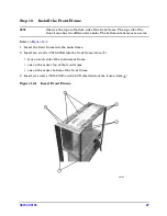
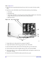
5. Insert the new rear panel into the frame. Be sure all wires are clear of the fan and the
frame.
6. Insert four screws (0515-0380), (item
④
). Each will include one of the following:
• screw only
• green/white wire
• cable clamp (1400-0017) secures the gray fan cable and the green/white wire. Orient the
clamp so that the flat side is toward the bottom of the instrument.
• black ground wire
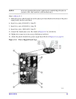
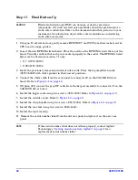
Figure 12-3 Rear Panel Cables
7. Connect the fan wire (blue and red) to connector J3 (item
⑤
).
8. Connect the thermal switch (item
⑥
) using two screws (0515-0372).
9. Insert the thermal switch cable into the cable clamp (item
⑦
) on the heat sink.
10. Secure the blue and red wires together (item
⑧
) with a tie wrap (1400-0249).
11. Secure the white/grey wires and the gray thermal switch wire together with a tie wrap
(1400-0249), (item
⑨
).
12. Insert four screws (0515-0380) on the top side of the rear panel.
Summary of Contents for 08757-60159
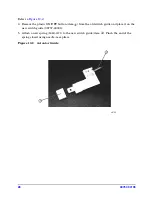
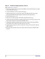
Page 43: ...08757 90195 43 Figure 16 1 Display Interface Board...
Page 46: ...46 08757 90195...


