


16
08757-90195
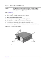
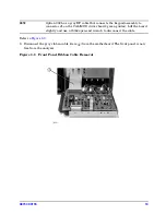
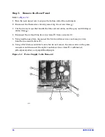
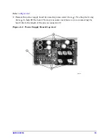
Step 5. Remove the Rear Panel
Refer to
Figure 5-1
.
1. Turn the instrument over to expose the bottom side of the instrument.
2. Disconnect the thermistor switch by removing two screws (item
①
).
3. Cut the two tie wraps that bundle the blue and red cables, and the gray and white/gray
cables (item
②
).
4. Disconnect the red and blue fan wires (item
③
) from connector J3.
5. Using needle-nose pliers, disconnect the five transformer wires and one gray wire
from the line module (item
④
).
6. Using a flat blade screwdriver loosen, but do not remove, the nine screws on the green
connectors and disconnect the eight transformer wires (item
⑤
): red/blue/red,
yellow/green/yellow, and purple/blank/purple.
Figure 5-1 Power Supply Cable Removal
Summary of Contents for 08757-60159
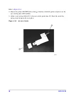
Page 43: ...08757 90195 43 Figure 16 1 Display Interface Board...
Page 46: ...46 08757 90195...


