


08757-90195
39
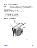
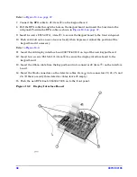
Step 14. Install the Keypad Assembly
Refer to
Figure 14-1
.
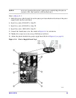
1. Connect the large gray ribbon cable to connector J1 (item
①
) on the motherboard.
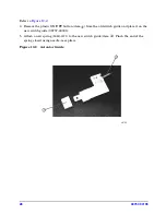
2. Connect the detector interface cables (item
②
) to the motherboard. Refer to
“Detector
Connectors” on page 11
for a more detailed image. (If there are only three detector cables,
leave J4 empty.)
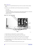
3. Option 002 has a gray RF connector on the front panel. Route this cable into the card cage
slot with green guides. It will be inserted into the CAL/MOD driver board later in this
procedure.
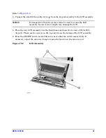
4. Insert the keypad assembly into the front frame.
5. Insert four screws (0515-1382). There are two screws on the top and two on the bottom of
the keypad assembly. Refer to
Figure 3-2 on page 12
.
Figure 14-1 Keypad Assembly
Summary of Contents for 08757-60159
Page 43: ...08757 90195 43 Figure 16 1 Display Interface Board...
Page 46: ...46 08757 90195...


