


42
08757-90195
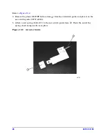
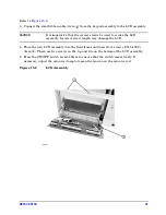
Step 16. Install the Display Interface Board
Refer to
Figure 16-1 on page 43
.
1. Place the new display interface board (85101-60293) into the LCD shield and insert eight
screws (0515-0430), (item
①
).
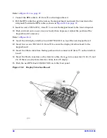
2. Connect the LCD data cable to connector J6 (item
②
).
3. Open the locking device on connector J7 (item
③
) by pulling the collar forward and
inserting the flat flex cable with the metal conductive traces facing upward.
4. Close the locking device on J7.
5. Insert the new rubber grommet (4320-0002) on the LCD shield (item
④
).
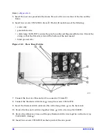
6. Connect the large ribbon cable from motherboard to connector J4 (item
⑤
) and secure with
the connector clip that was used on the old graphics board.
7. Connect the small ribbon cable from the rear panel to connector J2 (item
⑥
). Fold the
excess ribbon cable and place it into the clip on the rear panel.
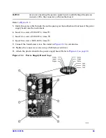
8. Connect the new white power-cable
to connector J3 (item
⑦
). The new power cable has
eight conductors.
9. Place the rubber grommet on the power supply cable into the notch on the LCD shield
(item
⑧
).
Summary of Contents for 08757-60159
Page 43: ...08757 90195 43 Figure 16 1 Display Interface Board...
Page 46: ...46 08757 90195...


