background image

Chapter 2 — Installing the scanner

26

Connecting the scanner

Before you connect the scanner to your Macintosh, make sure that your scanner as well as your
Macintosh and everything connected to it are switched off.

A terminator and a SCSI cable are supplied with your scanner. Apple Computer, Inc. recommends
using only its proprietary (Black) terminator for the Macintosh IIfx.

Caution: 

For safety reasons, never use extension cables for power cables.

Always make sure there are no more than two terminators in your SCSI chain, one at the beginning and one at

the end. Some SCSI devices have built-in terminators and must therefore be placed at the beginning or end of

your SCSI chain. Please check the documentation of each of your SCSI devices if you're not sure whether the

device has a built-in terminator. Your DuoScan has no built-in terminator.

If your DuoScan is the only SCSI device to be connected to your Apple
Macintosh:

1.

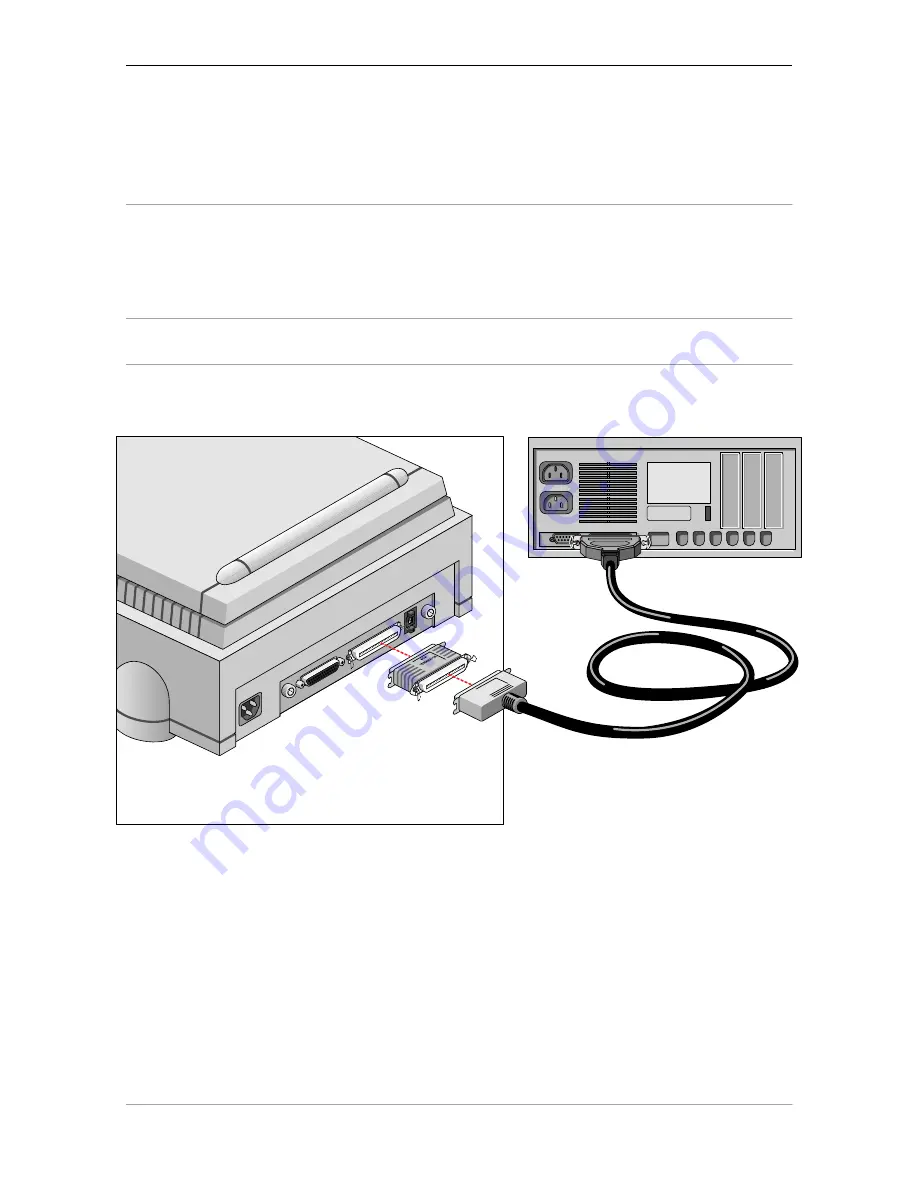
Place the terminator on the 50-pin connector of the scanner.

2.

Connect the smaller 25-pin end of the SCSI cable to the connector of your Apple Macintosh.

3.

Connect the larger 50-pin end of the SCSI cable to the free side of the terminator.

4.

Snap the diamond shaped wire clips into the clip brackets to secure the connection.

Summary of Contents for DuoScan

Page 1: ... shows you how to set up your DuoScan for the Apple Macintosh and PC Appendix A Troubleshooting This appendix can be helpful when you come across problems that you are unable to solve Appendix B Technical information This appendix provides specifications of your DuoScan Appendix C DuoScan regulation compliance This appendix gives you information on the safety regulations and on electromagnetic int...

Page 2: ...ncorporated PC is a registered trademark of the International Business Machines Corporation Windows 95 is a trademark of Microsoft Corporation Other product or company names are trademarks or registered trademarks of their respective holders Copyright 1996 Agfa Gevaert N V All rights reserved All software and hardware described in this document is subject to change without notice ...

Page 3: ...r 17 Performing a power on test 19 2 Installing the scanner 20 Minimum hardware requirements and recommendations 20 Environmental requirements 21 Precautions 22 Cleaning your scanner 22 SCSI devices 23 Installation for the Apple Macintosh 23 Choosing a SCSI ID number 24 Connecting the scanner 26 Testing the connection 29 Installation for the PC 30 Which SCSI interface card 30 Choosing a SCSI ID nu...

Page 4: ...e slide holder frame and the batch slide holders These allow you to scan transparent originals without using the reflective glass plate Three regular slide holders are supplied with DuoScan together with several types of batch slide holders which are available as an option in order to increase the productivity of the scanner Also new is the adjustable document cover for reflective scanning when yo...

Page 5: ...ing a power on test Unpacking the scanner 1 Open the packing box and carefully take out all the items 2 Check each item to make sure that there is no visual defect If something is missing or damaged contact your dealer or Agfa service representative 3 Remove the plastic wrapping and the packing materials from the scanner Note Save the packing materials so that you can repack the scanner to protect...

Page 6: ...ches around each side of the scanner and a minimum of 15 cm 6 inches at the rear side of the scanner Relocking the scanner If you need to transport the scanner you should relock your it This will protect the scanner s optical assembly from possible damage 1 Switch your scanner on 2 Pull the scanner forwards on the edge of the table until you can see the unlocking screw on the bottom of the scanner...

Page 7: ...so that you become familiar with its parts The figure front view illustrates the locations of the different parts of your DuoScan 1 4 5 7 6 8 3 2 1 reflective glass plate 2 adjustable document cover 3 transparency tray 4 power switch 5 reflective ready indicator 6 transparency ready indicator 7 power indicator 8 rulers ...

Page 8: ...canner 8 The figure rear view illustrates the location of the different parts at the rear of your scanner 5 1 2 3 4 2 1 power input 2 thumb wheel to pull out the main board 3 25 pin connector 4 50 pin connector 5 SCSI ID switch ...

Page 9: ...Chapter 1 Preparing the scanner 9 1 universal glass frame 2 batch slide holder frame 3 batch slide holders 3x 1 2 3 1 power cable 2 terminator 3 SCSI cable 2 3 1 ...

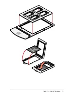
Page 10: ...ce of a CCD scanner is always best near the middle of the scan area However for the most common resolutions used for reflective originals placing originals to the side will not decrease quality 3 Close the document cover of the scanner Placing transparent originals When you scan transparent originals you use either a batch slide holder frame or the universal glass frame 1 2 1 universal glass frame...

Page 11: ... the slide holder frame when you put the universal slide holder on the slide holder frame of the scanner This position guarantees the best quality 2 Clip your original underneath the edge of the universal slide holder 3 Put the slide holder frame into the transparency tray with the Agfa logo at the upper side Note Make sure that the calibration slit of the slide holder frame is at the front side s...

Page 12: ...is directed towards the calibration slit of the slide holder frame This position guarantees the best quality 3 Fix the regular slide holder on the universal glass frame by pushing it firmly down the rear of the holder having a glass adhesive thereby securing it to the glass The holder can still be removed easily 4 Put the universal glass frame into the transparency tray with the Agfa logo facing u...

Page 13: ...lide into the frame 1 Locate the edge of the slide into the indented v on the arm of the holder 2 Push the slide down into the aperture 3 Ensure that the slide is secured by the six fixing lugs on the inside of the frame The slide position might need slight adjustment after location 4 When all the slides have been mounted locate the batch slide holder into the batch slide holder frame Remove a sli...

Page 14: ...Chapter 1 Preparing the scanner 14 ...

Page 15: ...he end of the holder and pushing the strip slide frame towards the hinge slot The frame will become loose 2 Lift the strip slide frame 3 Place the strip of slides into the centre of the frame 4 Close the frame 5 Lock the frame in position by sliding away from the hinge slot The position of the slides can be readjusted slightly by moving the slides within the holder Remove a slide from the frame 1 ...

Page 16: ...Chapter 1 Preparing the scanner 16 ...

Page 17: ... end of the holder and pushing the frame towards the hinge slot The frame will become loose 2 Lift the frame 3 Locate the slide against the front edge of the holder 4 Close the frame 5 Lock the frame in position by sliding it away from the hinge slot Remove a slide from the frame 1 Unlock the frame by placing your thumb on the raised points on the end of the holder and pushing the frame towards th...

Page 18: ...Chapter 1 Preparing the scanner 18 ...

Page 19: ...of the scanner corresponds with the voltage in your area If not call your dealer or Agfa service representative 3 Switch on the scanner The scanner performs a self test during which the power indicator light green switches on and the reflective ready indicator light yellow and the transparency ready indicator light yellow remain blinking This takes about half a minute After the self test the three...

Page 20: ...interface card Choosing a SCSI ID number Connecting the scanner Testing the connection Minimum hardware requirements and recommendations For the Apple Macintosh A Power PC processor A 13 inch color monitor 24 bit color display recommended 16 MB of RAM A high capacity disk drive The amount of disk space available on your Macintosh determines the number and size of the images you can scan Make sure ...

Page 21: ...d about two times the size of the image to scan edit and save an image You need a minimum of 30 MB free hard disk space and 8 MB of RAM for color images An IBM PC or compatible capable of running MS Windows Windows 95 or Windows NT Environmental requirements Place the scanner on a horizontal flat surface To ensure proper ventilation allow a minimum of 10 cm 4 inches free space around each side of ...

Page 22: ...d sensitive components Any corrective maintenance should be carried out by your dealer or Agfa service representative Do not leave originals on the reflective glass plate or on the slide holder frame for excessive periods of time The warmth of the scanner may cause them to deteriorate Make sure that the originals are properly attached on the glass plate otherwise you might loose them in the scanne...

Page 23: ...r or the device A unique SCSI ID number is assigned to each device in the SCSI chain enabling your computer to identify the device it wants to communicate with and the priority of each device Caution If two SCSI devices have the same ID number your system will not work properly and you may damage your SCSI devices To avoid crashes never use extension cables for SCSI cables Installation for the App...

Page 24: ... you installed the software 1 Copy the SCSI ID Checker to your Macintosh computer if not already done 2 Open the SCSI ID Checker A dialog box appears with a list of the SCSI ID numbers that are free in your Macintosh computer Your Macintosh always occupies ID 7 its internal hard disk usually occupies ID 0 or ID 1 and CD ROM usually occupies ID 3 If your Macintosh is equipped with 2 SCSI busses the...

Page 25: ...D number n Make sure your scanner is switched off and is disconnected from your computer n Decide on an unassigned SCSI ID number n Use the SCSI ID switch see figure at the rear of the scanner to set the desired SCSI ID Push above the SCSI ID number to decrease the number push underneath the SCSI ID number to increase the number 5 Click OK to close the SCSI ID Checker ...

Page 26: ...at the beginning and one at the end Some SCSI devices have built in terminators and must therefore be placed at the beginning or end of your SCSI chain Please check the documentation of each of your SCSI devices if you re not sure whether the device has a built in terminator Your DuoScan has no built in terminator If your DuoScan is the only SCSI device to be connected to your Apple Macintosh 1 Pl...

Page 27: ...ove the terminator from the last device in the SCSI chain 2 Connect the 50 pin end of the SCSI cable to the connector that has become available on this device 3 Place the terminator on the free 50 pin connector of the scanner 4 Connect the 25 pin end of the SCSI cable to the free connector of the scanner 5 Snap the diamond shaped wire clips into the clip brackets to secure the connection ...

Page 28: ...evices 2 Connect the free end of this SCSI cable to the scanner 3 Connect the 50 pin end of the SCSI cable the one supplied with your scanner to the other adjacent SCSI device 4 Connect the 25 pin end of the SCSI cable the one supplied with your scanner to the scanner 5 Snap the diamond shaped wire clips into the clip brackets to secure the connection ...

Page 29: ...st the power indicator light switches on and the two other indicator lights start blinking After the self test all the scanner s indicator lights switch on 4 Switch on any other SCSI devices you may have attached and wait for them to start up 5 Switch on your Macintosh As it starts up your Macintosh performs a series of tests to verify the correct system configuration 6 Open the SCSI ID checker 7 ...

Page 30: ...ion The Read Me file on the PC scanner driver software disk for up to date information The documentation supplied with your interface card This will tell you how to install the card If you are using third party software check the documentation supplied with that software for the SCSI interface cards supported Choosing a SCSI ID number Before you connect your DuoScan to your PC you have to find out...

Page 31: ...to a free SCSI ID number n Make sure your scanner is switched off and is disconnected from your computer n Decide on an unassigned SCSI ID number n Use the SCSI ID switch at the rear of the scanner to set the desired SCSI ID Push above the SCSI ID number to decrease the number push underneath the SCSI ID number to increase the number 4 Close Show SCSI ...

Page 32: ...ors and must therefore be placed at the beginning or end of your SCSI chain Please check the documentation of each of your SCSI devices if you re not sure whether the device has a built in terminator Your DuoScan has no built in terminator Never try to connect the scanner to the serial or parallel port of your PC you might seriously damage your equipment if you do If your PC has a high density con...

Page 33: ...the SCSI cable to the free connector of the scanner If your PC has a 50 pin connector and your DuoScan will be connected to your PC together with other SCSI devices n If you install the scanner at the end of your SCSI chain 1 Set the scanner to an unused SCSI ID number between 1 and 6 For more information see Choosing a SCSI ID number earlier in this chapter 2 Connect the 50 pin end of the SCSI ca...

Page 34: ...r in this chapter 3 Connect the 50 pin end of the SCSI cable to the connector at the rear of the adjacent device Use the cable supplied with the scanner 4 Connect the 25 pin end of the cable to the scanner s 25 pin connector 5 Connect the scanner to the next device in the SCSI chain 6 Make sure that the last device in the chain is terminated Caution In this configuration you are not allowed to put...

Page 35: ...if the SCSI cable is properly connected 3 Switch the scanner on The scanner performs a self test the power indicator light green switches on and the ready indicator lights yellow start blinking After the self test the scanner s power indicator light switches on 4 Switch on any other SCSI devices you may have attached and wait for them to start up 5 Switch on your PC 6 Check in Show SCSI if the SCS...

Page 36: ...l remains blinking or goes off after the power up sequence about half a minute A malfunction has been detected by the scanner Check if you have unlocked the scanner If this can not be the problem please contact your dealer or Agfa service representative The power indicator fails to light up Verify the power connection to the scanner Check if the power switch is turned on If you have confirmed that...

Page 37: ...on Therefore try restarting your workstation If this doesn t help Disconnect all SCSI devices and connect them one by one beginning with the scanner to identify the device that causes the problem The scanner reports errors during scanning Apple Macintosh Check the presence of the SCSI terminator If this can not be the problem please contact your dealer or Agfa service representative When starting ...

Page 38: ... Conversion 36 bit 12 bit per color Output pixel depth 1 bit output for line art black and white 8 or 12 bit output for gray 24 or 36 bit output for color Density range 3 2 D Max density detected 3 4 D Scanning speed 7 14 ms line Original sizes A4 or Legal Maximum scan area Maximum reflection 8 x 14 inch 203 x 355 mm Maximum transmission 8 x 10 inch 203 x 254 mm transparency Memory 1 Mb RAM Reflec...

Page 39: ...sumption 40 W Dimensions 400 mm 16 inch x 182 mm 7 inch x 613 mm 24 inch W x H x L Weight 13 5 kg Acoustic noise max 55 dB in worst condition Interface SCSI 2 interface Maximum throughput 4 MB sec Environment Operating temperature 10 C to 40 C 50 F to 104 F Relative humidity 10 to 85 ...

Page 40: ...igung zur Überprüfung der Serie auf Einhaltung der Bestimmungen eingeraumt TÜV Wichtige Sicherheitshinweise 1 Bitte Lesen Sie sich diese Hinweise sorgfältig durch 2 Um eine Beschädigung des Gerätes zu vermeiden sollten Sie nur Zuberhörteile verwenden die vom Hersteller zugelassen sind 3 Das Gerät ist vor Feuchtigkeit zu schützen 4 Bei der Aufstellung des Gerätes ist auf sicheren Stand zu achten Ei...

Page 41: ...s cause harmful interference to radio or television reception which can be determined by turning the equipment off and on the user is encouraged to try to correct the interference by one or more of the following measures Reorient or relocate the receiving antenna Increase the separation between the equipment and receiver Connect the equipment into an outlet on a circuit different from that to whic...

Reviews: