background image

36

MAKING CONNECTIONS

2.7 IR Co n n e c t i o n

Connect the IR sensor cable to the IR IN connector of the LCD display.

[ I R   I N ]

E x t e r n a l

I R   R e c e i v e r

DISPLAY

No t e :

  This display’ s remote control sensor will stop working if the [ IR IN]  is connected.

  IR loop through connection can support up to 9 displays. 

  IR in daisy chain via RS232 connection can support up to 9 displays.

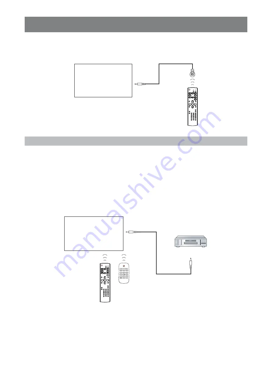
2.8 IR Pa s s - Th r o u g h  Co n n e c t i o n

Connect one end of an IR extender cable to the IR OUT connector of the LCD display and the other end of an 

IR extender cable to the IR IN connector of the video player.

Video Player

(Video Player)

Remote Control

[ IR OUT]

[ IR IN]

DISPLAY

Summary of Contents for QM-65A

Page 1: ...QM 65A QM 75A QM 86A LED Backlit Display User Manual displays agneovo com ...

Page 2: ...he Installation 11 1 4 Wall Mounting Installation 11 1 4 1 VESA Grid 12 1 4 2 Ventilation Requirements for Enclosure Locating 13 1 5 Using the Remote Sensor and Power Status Indicator 13 1 6 LCD Display Overview 14 1 6 1 Control Panel 14 1 6 2 Input Output Terminals 16 1 7 Remote Control 18 1 7 1 General Functions 18 1 7 2 ID Remote Control 20 1 7 3 Remote Control buttons on Android source 21 1 7 ...

Page 3: ...1 4 2 2 Modifying a Playlist 43 4 2 3 Playing Files in a Playlist 43 4 2 4 Media Player Settings 43 4 3 Browser 44 4 3 1 Adding an URL 44 4 3 2 Managing URLs List 46 4 4 Content Management Software CMS 47 4 4 1 Using a CMS Server for Content Source 48 4 4 2 Displaying Content from an Attached Storage Device 49 4 5 PDF Player 50 4 5 1 Creating a Playlist 50 4 5 2 Modifying a Playlist 52 4 5 3 Displ...

Page 4: ...uration1 Settings 71 6 5 Configuration2 Settings 74 6 6 Advanced option Settings 76 CHAPTER 7 APPENDIX 87 7 1 Warning Messages 87 7 2 Supported Media Formats 87 7 3 Input Mode 89 7 4 Cleaning 91 7 5 Troubleshooting 92 7 6 Transporting the LCD Display 93 CHAPTER 8 SPECIFICATIONS 96 8 1 Display Specifications 96 8 2 Display Dimensions 97 ...

Page 5: ...ure THIS CLASS A DIGITAL APPARATUS MEETS ALL REQ UIREMENTS OF THE CANADIAN INTERFERENCE CAUSING EQ UIPMENT REGULATIONS This device complies with part 15 of the FCC Rules Operation is subject to the following two conditions 1 This device may not cause harmful interference and 2 this device must accept any interference received including interference that may cause undesired operation CE W ARNING Th...

Page 6: ...roducts to comply with all applicable legal requirements and to stay well within the EMF standards applicable at the time of producing the products We are committed to develop produce and market products that cause no adverse health effects e confir that if its products are handled properly for their intended use they are safe to use according to scientific e idence a aila le today We play an acti...

Page 7: ...hould be a BS 1362 5A A S T A or BSI approved type 3 efit the fuse co er f the fitted plug is not suita le for your soc et outlets it should e cut off and an appropriate pin plug fitted in its place If the mains plug contains a fuse this should have a value of 5A If a plug without a fuse is used the fuse at the distribution board should not be greater than 5A Note The severed plug must be destroye...

Page 8: ...L or coloured RED Before replacing the plug cover make certain that the cord grip is clamped over the sheath of the lead not simply over the three wires No r t h Eu r o p e No r d i c Co u n t r i e s In f o r m a t i o n Placering Ventilation V ARNING FÖ RSÄ KRA DIG OM ATT HUVUDBRY TARE OCH UTTAG Ä R LÄ TÅ TKOMLIGA NÄ R DU STÄ LLER DIN UTRUSTNING PÅ PLATS Placering Ventilation ADV ARSEL SØ RG VED...

Page 9: ...organi ation that ser es your household or the store at hich you purchased the product At t e n t i o n u s e r s i n Un i t e d St a t e s Please dispose of according to all Local State and Federal Laws For the disposal or recycling information contact www mygreenelectronics com or www eiae org En d o f Li f e Di r e c t i v e s Re c y c l i n g Y our new Public Information Display contains sever...

Page 10: ...e contact your local authority for details on the collection and recycling schemes or S it erland The used attery is to e returned to the selling point For other non EU countries Please contact your local authority for correct method of disposal of the used battery According to EU directive 2006 66 EC the battery can t be disposed improperly The battery shall be separated to collect by local servi...

Page 11: ... o v o c o m To protect your rights as a consumer do not remove any stickers from the LCD display Doing so may affect the determination of the warranty period Ca u t i o n s W h e n Se t t i n g Up Do not place the LCD display near heat sources such as a heater exhaust vent or in direct sunlight Do not cover or block the ventilation holes in the housing Place the LCD display on a stable area Do no...

Page 12: ...et hands When turning off the display by detaching the power cord wait 6 seconds before re attaching the power cord for normal operation Do not knock or drop the display during operation or transportation Cl e a n i n g a n d Ma i n t e n a n c e To protect your display from possible damage do not put excessive pressure on the LCD panel When moving your display grasp the frame to lift do not lift ...

Page 13: ...off the LCD display for extended periods of time It can be several hours or several days Use a screen saver and run it for extended periods of time Use a black and white image and run it for extended periods of time There are millions of micro transistors inside the LCD display It is normal for a few transistors to be damaged and to produce spots This is acceptable and is not considered a failure ...

Page 14: ... with the safety regulations of the particular country Type H05W F 2G or 3G 0 75 or 1 mm2 should be used Y ou might like to save the package box and packing material for shipping the display The pictures are for reference only Actual items may vary upon shipment HDMI c a b l e CHAPTER 1 PRODUCT DESCRIPTION 1 1 Un p a c k i n g This product is packed in a packaging box which contains standard acces...

Page 15: ...the kitchen bathroom or any other places with high humidity so as not to shorten the service life of the electronic components The product can normally operate only under 3000m in altitude In installations at altitudes above 3000m some abnormalities may be experienced W a r n i n g Do not press too hard on the LCD panel or edge of the frame as this may cause the device to malfunction No t e Avoid ...

Page 16: ...natural disaster be sure to consult the bracket manufacturer for installation location No t e For Q M 65A wall mounting kits use M6 mounting screws having a length 10 mm longer than the thickness of the mounting bracket and tighten them securely For Q M 75A Q M 86A wall mounting kits use M8 mounting screws having a length 15 mm longer than the thickness of the mounting bracket and tighten them sec...

Page 17: ...n d Po w e r St a t u s In d i c a t o r If you want to obtain a better reception of remote control function please adjust the indicator location to easily check the power status indicator If you want to mount the display to the wall please push the indicator switch upwards before installation hen ad usting the indicator location a e sure to push pull the indicator s itch fir ly until it clic s in...

Page 18: ...14 PRODUCT DESCRIPTION 1 6 LCD Di s p l a y Ov e r v i e w 1 6 1 Co n t r o l Pa n e l Q M 65A MUTE INPUT MENU 1 9 2 3 4 5 6 7 8 Q M 75A MUTE INPUT MENU 1 9 2 3 4 5 6 7 8 ...

Page 19: ...the highlight bar down to select an option or decrease the adjustment while OSD menu is on 8 MENU Activate the OSD menu when OSD menu is off Hide the OSD menu while OSD menu is on 9 Re m o t e c o n t r o l s e n s o r a n d p o w e r s t a t u s i n d i c a t o r Receive command signals from the remote control Indicate the operating status of the display Lights green when the display is turned on...

Page 20: ...16 PRODUCT DESCRIPTION 1 6 2 In p u t Ou t p u t Te r m i n a l s Q M 65A 1 16 2 3 4 5 6 7 9 8 10 13 14 15 11 12 7 Q M 75A 1 2 3 4 5 6 7 9 8 10 13 14 15 11 12 7 ...

Page 21: ...the IR IN jack is connected To remotely control your A V device via this display see page 36 for IR Pass Through connection 9 IR OUT IR signal output for the loop through function 10 V GA IN D Su b VGA video input 11 AUDIO IN Audio input for VGA source 3 5mm stereo phone 12 AUDIO OUT Audio output to external AV device RCA 13 USB 2 0 3 0 PORT Connect your USB storage device USB 2 0 x 1 Service Port...

Page 22: ...Go to Smart picture OSD Main Menu Move the highlight bar up to adjust the selected item IR Daisy Chain Menu Increase controlled Group ID number Root Menu Go to Audio source OSD Main Menu Move the highlight bar down to adjust the selected item IR Daisy Chain Menu Decrease controlled Group ID number Main Menu Return to the previous menu page Source Menu Exit the source menu Volume Menu Decrease the ...

Page 23: ...n function 11 Nu m b e r ID SET ENTER Enter text for network setting Set the display ID See 1 7 2 ID Remote Control for more detail 12 FORMAT Change the aspect ratio 13 B ACK Return to the previous menu or exit from the previous function 14 INFO View the information about the display 15 OPTIONS No function 16 V OLUME Adjust the volume level ...

Page 24: ...elect the display you want to control For example Display ID 1 press 0 1 Display ID 11 press 1 1 The numbers available are from 01 255 Not pressing any button within 10 seconds will exit the ID mode If an error pressing of buttons other than the digits occured wait 1 second after the red LED lights off and then lights up again then press the correct digits again 4 Press the ENTER button to confir ...

Page 25: ...d select it to play 2 PDF Pl a y e r Pl a y choose non empty playlist press the button to play all the PD files in the playlist 3 Set pdf playlist in Boot on Source or Schedule by OSD menu hen playing the PD or ideo file press the button to stop playing Press the utton to replay the edia file fro the beginning hen playing PD or ideo file press the button to pause playing ll edia files should e put...

Page 26: ...hese two buttons are only controlled by Scalar hen ro sing the PD files Perform zo om in Perform zo om out After zo om in or zo om out press the utton to re ert the pdf file to the original size 11 Nu m b e r ID SET ENTER ID SET ENTER No function on Android source These two buttons are only controlled by Scalar hen ro sing the PD files enter the page number by pressing number buttons and then pres...

Page 27: ...when pressing a button When using the remote control the distance from the remote control to the sensor on the display should be less than 5m 16ft and the hori ontal and ertical angles should e less than Q M 65A Q M 75A 30 30 Ca u t i o n The incorrect use of batteries can result in leaks or bursting Be sure to follow these instructions Place AAA batteries matching the and signs on each battery to...

Page 28: ...24 PRODUCT DESCRIPTION Q M 86A 30 30 ...

Page 29: ...nnect one end of the power cord to the AC IN connector at the rear of the LCD display 2 Connect the other end of the power cord to a power outlet or a power supply 3 Set the Ma i n Po w e r switch to ON CHAPTER 2 MAKING CONNECTIONS Q M 65A Q M 75A ...

Page 30: ... display is not connected to the power outlet before making any connections Connecting cables while the power is ON may cause electric shock or personal injury When unplugging the power cord hold the power cord by the plug head Never pull by the cord Q M 86A ...

Page 31: ...cable to the VGA OUT D Sub connector of the computer For audio input connect one end of an audio cable to the AUDIO IN connector of the LCD display and the other end of an audio cable to the AUDIO OUT connector of the computer V G A O U T D S ub 15 pi n V G A I N A U D I O O U T A U D I O I N C om puter Q M 65A V G A O U T D S ub 15 pi n V G A I N A U D I O O U T A U D I O I N C om puter Q M 75A ...

Page 32: ...I N C om puter 2 2 2 Us i n g Di s p l a y Po r t In p u t Connect one end of a DisplayPort cable to the DisplayPort IN connector of the LCD display and the other end of a DisplayPort cable to the DisplayPort OUT connector of the computer D isplayP ort O U T D isplayP ort I N C om puter Q M 65A ...

Page 33: ...29 MAKING CONNECTIONS D isplayP ort O U T D isplayP ort I N C om puter Q M 75A D isplayP ort O U T D isplayP ort I N C om puter Q M 86A ...

Page 34: ... HDMI cable to the HDMI IN connector of the LCD display and the other end of an HDMI cable to the HDMI OUT connector of the computer H D M I I N C om puter H D M I O U T Q M 65A H D M I I N H D M I O U T H D M I I N C om puter H D M I O U T Q M 75A H D M I I N H D M I O U T ...

Page 35: ...V ideo Playe r 2 3 Co n n e c t i n g Ex t e r n a l Eq u i p m e n t V i d e o Pl a y e r 2 3 1 Us i n g HDMI V i d e o In p u t Connect one end of an HDMI cable to the HDMI IN connector of the LCD display and the other end of an HDMI cable to the HDMI OUT connector of the video player Q M 65A H D M I O U T H D M I I N ...

Page 36: ...32 MAKING CONNECTIONS H D M I I N H D M I O U T V ideo Playe r Q M 75A H D M I O U T H D M I I N H D M I I N H D M I O U T V ideo Playe r Q M 86A H D M I O U T H D M I I N ...

Page 37: ... i c e Connect one end of an audio cable to the AUDIO OUT connectors of the LCD display and the other end of an audio cable to the AUDIO IN connectors of the audio device A U D I O O U T A udio D evice A U D I O I N Q M 65A A U D I O O U T A udio D evice A U D I O I N Q M 75A A U D I O O U T A udio D evice A U D I O I N Q M 86A ...

Page 38: ...S 2 5 Us i n g t h e Ca r d Re a d e r Insert a micro SD card into the slot M I C R O S D C A R D S L O T M icro S D Q M 65A M I C R O S D C A R D S L O T M icro S D Q M 75A M I C R O S D C A R D S L O T M icro S D Q M 86A ...

Page 39: ... n To avoid unnecessary strain on the beze l it is highly recommended to keep a minimum space of 0 5mm in which a business card is able to slip between all displays on all sides 0 5 mm 2 6 1 Di s p l a y Co n t r o l Co n n e c t i o n Connect the RS232 OUT connector of DISPLAY 1 to the RS232 IN connector of DISPLAY 2 D I S P L A Y 1 P C D I S P L A Y 2 R S 232 I N R S 232 R S 232 O U T R S 232 I ...

Page 40: ...ing if the IR IN is connected IR loop through connection can support up to 9 displays IR in daisy chain via RS232 connection can support up to 9 displays 2 8 IR Pa s s Th r o u g h Co n n e c t i o n Connect one end of an IR extender cable to the IR OUT connector of the LCD display and the other end of an IR extender cable to the IR IN connector of the video player Video Player Video Player Remote...

Page 41: ...l consumes power as long as the power cord is connected to the power outlet Disconnect the power cord to completely cut off power CHAPTER 3 USING THE LCD DISPLAY POW ER button 3 1 1 In i t i a l Se t u p After you turn on the LCD display a Welcome screen opens Y ou are pro pted to select the default SD language configure net or settings and more Follow the on screen instructions to complete the in...

Page 42: ...yer Browser CMS PDF Player Custom If the selected input source signal is not connected to the LCD display or is turned off the screen will display multi color screen 1 Press the button 2 Press the or button to choose a device then press the button SOURCE button 3 3 Ad j u s t i n g t h e V o l u m e Press the or button to adjust the volume No t e After pressing the or button the volume icon is dis...

Page 43: ...tted in 16 9 using the full screen display 4 3 The picture is reproduced in 4 for at and a lac and is displayed on either side of the picture Re a l This mode displays the image pixel by pixel on screen without scaling the original image size 21 9 The picture is reproduced in 21 for at and a lac and at the top and bottom Cu s t o m Choose to apply the custom zo om settings set in the Sc r e e n Cu...

Page 44: ...ite s such as Media Player ro ser CMS PD Player and Custo To access the ulti edia enu ite s do the follo ing HDMI1 HDMI2 HDMI3 HDMI4 DisplayPort VGA OPS Media Player Browser CMS HDMI3 HDMI4 DisplayPort VGA OPS Media Player Browser CMS PDF Player Custom 1 Press the button to open a list of input sources 2 Press the or button to select Me d i a Pl a y e r B r o w s e r CMS PDF Pl a y e r or Cu s t o...

Page 45: ...torage agn photo ideo root dir of storage agn ideo Music root dir of storage agn usic No t e Music files can e selected and used as ac ground usic for a slidesho 2 Connect the storage de ice to the CD onitor if necessary 3 Set the input source to Me d i a Pl a y e r See 4 1 ccessing the Multi edia Menu 4 Press the or button to select the Co m p o s e tab and then press the utton to open the Play i...

Page 46: ...3927 JPG Then press the or button and press the utton to select any of the follo ing actions Se l e c t a l l Select all the isi le edia files on the storage de ice De l e t e a l l Delete all the edia files in the playlist Ad d Re m o v e dd or re o e the selected files fro the playlist So r t Sort the edia files in the playlist one y one The Sort enu opens a Press the or button and then press th...

Page 47: ...s as descri ed in steps and in 4 2 1 Creating a Playlist section 4 2 3 Pl a y i n g Fi l e s i n a Pl a y l i s t To play files in a playlist do the follo ing 1 Set the input source to Me d i a Pl a y e r See 4 1 ccessing the Multi edia Menu 2 Press the or button to select the Pl a y tab and then press the utton to open the Play ist menu 3 Press the or button to select the playlist that you want t...

Page 48: ...d Co r n e r or No n e and then press the utton to sa e the setting Settings Repeat Mode Slideshow Effect Effect Duration 5s 10s 15s 20s Ef f e c t Du r a t i o n Press the or button to set the slideshow effect duration to 5s 10s 15s or 20s and then press the utton to sa e the setting 4 3 B r o w s e r se the ro ser app to sa e up to se en oo ar s s anually or i port a list of s fro a storage de i...

Page 49: ... na e fter selecting a character press the utton to enter the character Continue this step until all the characters in the are entered d Press the utton to close the irtual ey oard e Press the button and select OK to sa e the or Ca n c e l to discard the odifications Then press the utton to confir the selection Ad d i n g a URL a u t o m a t i c a l l y a Sa e a list of s in a te t file ith the e ...

Page 50: ... the or utton to select the te t file here are sa ed the s Then press the utton ou are pro pted to confir i porting the file or cancel the procedure i Press the or button to select Im p o r t or Ca n c e l and then press the button fter i porting the te t file the s appear in the s list in the ro ser app 4 3 2 Ma n a g i n g URLs Li s t To anage s list on ro ser app do the follo ing 1 Set the inpu...

Page 51: ...opens on the screen 5 Press the or button and then press the utton to do any of the follo ing Ex p o r t Press the or utton to select the storage de ice here you ant to sa e the current s list Then press the utton fter selecting the storage de ice you are pro pted to confir the location and the file na e of the s list Press the or button to Sa v e or Ca n c e l the procedure No t e f you ish to sa...

Page 52: ...utton to select the Se t t i n g s tab and then press the button 5 Press the or button and then press the button to select Si g n a g e Di s p l a y So u r c e s e t t i n g s CMS V e r s i o n 6 Press the or button and then press the utton to select and configure the CMS Ser er connection para eters such as Se t t i n g s Se r v e r Ac c o u n t PIN Co d e No t e fter the connection para eters ar...

Page 53: ...n CMS 2 Connect the storage de ice to the CD onitor if necessary 3 Set the input source to Cu s t o m See 4 1 ccessing the Multi edia Menu 4 nter the d in Mode See 4 6 1 ntering the d in Mode on page 5 5 Press the or button to select the Se t t i n g s tab and then press the button 6 Press the or button and then press the button to select Si g n a g e Di s p l a y So u r c e s e t t i n g s CMS V ...

Page 54: ...torage de ice to the follo ing path root dir of storage agn pdf 2 Connect the storage de ice to the CD onitor if necessary 3 Set the input source to PDF Pl a y e r See 4 1 ccessing the Multi edia Menu 4 Press the or button to select the Co m p o s e tab and then press the utton to open the Play ist menu Media Player 1920x1080 60Hz PlayList File 1 File 2 File 3 File 4 File 5 File 6 File 7 5 Press t...

Page 55: ...r OK Then press the or button and press the utton to select any of the follo ing actions Se l e c t a l l Select all the PD files on the storage de ice De l e t e a l l Delete all the files in the playlist Ad d Re m o v e dd or re o e the selected files fro the playlist So r t Sort the PD files in the playlist one y one The Sort enu opens a Press the or button and then press the utton to select th...

Page 56: ...escri ed in steps to in 4 5 1 Creating a Playlist section 4 5 3 Di s p l a y i n g PDF Fi l e s i n a Pl a y l i s t To display the PD files in a playlist do the follo ing 1 Set the input source to PDF Pl a y e r See 4 1 ccessing the Multi edia Menu 2 Press the or button to select the Pl a y tab and then press the utton to open the Play ist menu 3 Press the or button to select the playlist that yo...

Page 57: ...e the setting Settings Repeat Mode Effect Duration 5s 10s 15s 20s 4 6 Cu s t o m n Custo screen you can enter the d in Mode The d in Mode ena les you full access to the syste configuration settings applications net or configuration para eters and storage The default Custo screen is e pty to pre ent unauthori ed access to the syste 4 6 1 En t e r i n g t h e Ad m i n Mo d e To enter the d in Mode d...

Page 58: ...tings Net or thernet thernet Config ration e ie M C address and configure the net or connection settings such as Co n n e c t i o n Ty p e D CP or static P IP Ad d r e s s Ne t m a s k DNS Ad d r e s s and Ga t e w a y De v i c e Si g n a g e Di s p l a y Ge n e r a l s e t t i n g s Si g n a g e Di s p l a y Na m e e ie or odify the signage display na e if necessary De v i c e Si g n a g e Di s p...

Page 59: ...a y So u r c e s e t t i n g s CMS Se t t i n g s Configure CMS Ser er connection settings such as Se r v e r Ac c o u n t PIN Co d e and V e r s i o n er 2 or er or ore infor ation on CMS see 4 4 Content Manage ent Soft are CMS on page 4 De v i c e Si g n a g e Di s p l a y So u r c e s e t t i n g s CMS Co n t e n t Select the CMS content fro a storage de ice such as In t e r n a l s t o r a g e...

Page 60: ...ring the d in Mode on page 5 2 Press the or button to select the Ap p s tab and then press the button The apps screen opens 3 Press the or button to select the app and then press the button to open the app 4 6 4 In s t a l l i n g Ap p s t o t h e LCD Mo n i t o r To install ne apps to your CD onitor do the follo ing 1 Do nload and copy the ndroid installation file na ed ap here is the app s na e ...

Page 61: ...e r n e t tab and then press the button to start configuring the connection settings No t e The i i configuration settings are isi le only if you ha e connected a co pati le i i dongle to the CD display or a ireless connection M Series displays are co pati le ith follo ing i i dongles TP N T N 25N TP N rcher T4 and D N D 182 D1 4 6 6 Ma n a g i n g St o r a g e i n Ad m i n Mo d e To access and an...

Page 62: ...utton to complete the procedure Mo v e Press the or utton and select the destination storage de ice here you ant to o e the file Then press the button to complete the procedure Se l e c t nter the file Select Mode Press the or button and then press the button to select file s fter the file selection is done press the button Then press the or button to select an action fro the pop up enu a ong De l...

Page 63: ...ve Native Action Off Off Action Picture Screen Audio Configuration 1 Configuration 2 Advanced option The highlighted item blue indicates the active submenu 1 Press the or button to select the menu item 2 Press the button to enter the submenu 1 Press the or button to select the menu item 2 Press the or button to enter the submenu 3 Adjust the settings For example Black level 50 1 Press the or butto...

Page 64: ...n or button several times Press the button or the button several times hen settings are odified all changes are sa ed hen the user does the follo ing Proceeds to the another menu Exits the OSD menu Waits for the OSD menu to disappear No t e aila ility of so e enu ite s depend on the input source signal f the enu is not a aila le it is disabled and grayed out ...

Page 65: ...power Overscan Picture reset See page 63 2 Screen H position V position Clock Clock phase Z oom mode Custom zo om Auto adjust Screen reset See page 67 Brightness Contrast Sharpness Black level Tint Color Noise reduction Gamma selection Color temperature Color control Smart power Overscan 90 50 20 50 50 55 Medium Native Native Action Off Off Picture Screen Audio Configuration 1 Configuration 2 Adva...

Page 66: ...S232 routing Boot on source WOL RGB Range Configuration1 reset Factory reset See page 71 5 Configuration2 OSD turn off OSD H position OSD V position Information OSD Logo Monitor ID Heat status Monitor information HDMI Version Configuration2 reset See page 74 6 Advanced option IR control Power LED light Keyboard control Off Timer Date and time Schedule HDMI with One Wire Language OSD Transparency P...

Page 67: ...elect an option 4 Press the button on the control panel or the button on the remote control to open the submenu item It e m Fu n c t i o n Op e r a t i o n Ra n g e Brightness Adjust the luminance of the screen image Press the button on the control panel or the button on the remote control to adjust the value 0 to 100 Orig inal Setting H ig h Setting L ow Setting Contrast Adjust the difference bet...

Page 68: ... the button on the remote control to select the setting 2 Press the button on the control panel or the button on the remote control to set the value Off Low Medium High N oise Red uction Of f N oise Red uction On Gamma selection Adjust the non linear setting for picture luminance and contrast 1 Press the button on the control panel or the button on the remote control to open the settings 2 Press t...

Page 69: ...K 5 Press the button on the control panel or the button on the re ote control to confir the setting 6500K 7500K 9300K 10000K Native User 1 User 2 OK Cancel Color control Adjust the color tones of the image precisely by changing the User R Red User G Green and User B Blue settings independently No t e Color control option becomes available if you set the Color temperature to Us e r 1 or Us e r 2 1 ...

Page 70: ...setting 2 Press the button on the control panel or the button on the remote control to set the value Off Medium High Overscan Change the display area of the image On Display area is about 95 Off Display area is about 100 1 Press the button on the control panel or the button on the remote control to select the setting 2 Press the button on the control panel or the button on the remote control to se...

Page 71: ...tton on the remote control to select an option 4 Press the button on the control panel or the button on the remote control to open the submenu item It e m Fu n c t i o n Op e r a t i o n Ra n g e H position Move the image to the right or left No t e This option is available only if the input source is VGA Press the button on the control panel or the button on the remote control to adjust the value...

Page 72: ...ntrol to select CANCEL or OK 5 Press the button on the control panel or the button on the re ote control to confir the setting Full 4 3 Real 21 9 Custom Cancel OK Custom zo om Use this function to further customize the zo om settings to suit the image you want to display No t e This option is not available in the following modes Media Player Browser CMS PDF Player and Custom Z oom Expand the horiz...

Page 73: ...u d i o Se t t i n g s Balance Treble Bass Volume Audio out line out Maximum volume Minimum volume Mute Audio source Audio reset Audio Out Sync 50 50 50 20 20 100 0 Off Digital Action Off Picture Screen Audio Configuration 1 Configuration 2 Advanced option 1 Press the MENU button on the control panel or the button on the remote control to call out the OSD window 2 Press the button on the control p...

Page 74: ...etting 0 to 100 Mute Turn the mute function on off Press the MUTE button on the control panel or the button on the remote control to set the value Off On Audio source Select the audio input source There are no audio output when no video signal Analog Audio from audio input Digital Audio from HDMI audio 1 Press the button on the control panel or the button on the remote control to select the settin...

Page 75: ...e button on the remote control to select Config ration Then press the button on the control panel or the button on the remote control 3 Press the button on the control panel or the button on the remote control to select an option 4 Press the button on the control panel or the button on the remote control to open the submenu item It e m Fu n c t i o n Op e r a t i o n Ra n g e Switch on state Selec...

Page 76: ... shift the position of pixels in four directions up down left or right No t e Activating Anti Burn inTM will disable H Position V Position and Z oom Mode in the Screen Menu Press the button on the control panel or the button on the remote control to adjust the value Off Auto 10 to 900 Seconds RS232 Routing Select the network control port 1 Press the button on the control panel or the button on the...

Page 77: ...list If you set another input then follow steps 4 to 5 4 Press the button on the control panel or the button on the remote control Then press the button on the control panel or the button on the remote control to select CANCEL or OK 5 Press the button on the control panel or the button on the remote control to set the value HDMI1 HDMI2 HDMI3 HDMI4 DisplayPort VGA OPS Media Player Browser CMS PDF P...

Page 78: ...n on the remote control to set the value CANCEL RESET Factory reset Reset all your customize d settings to the factory preset values including Android settings CANCEL RESET Config ration ettings OSD turn off OSD H position OSD V position Information OSD Logo Monitor ID Heat status Monitor information HDMI Version Configuration2 reset 45 50 50 10 On Action 25 88 C 78 59 F Action 1 4 Action Picture ...

Page 79: ...et to On then the OTS logo will show If Log is set to Of f then the scalar OTS logo will not show If Logo is set to Us e r then there will be no boot logo when power on Logo will not rotate with rotation setting detection 1 Press the button on the control panel or the button on the remote control to select the setting 2 Press the button on the control panel or the button on the remote control to s...

Page 80: ... button on the control panel or the button on the remote control to set the value CANCEL RESET 6 6 Ad v a n c e d o p t i o n Se t t i n g s IR control Power LED Light Keyboard control Off timer Date and time Schedule HDMI with One Wire Language OSD transparency Power Save OPS settings Advanced option reset Unlock On Unlock Off Action Action Off English Off Mode 1 Auto Action Picture Screen Audio ...

Page 81: ...only receive the control signal from the primary display via the RS232 connection Lock All Lock all but Volume Lock all but Power Lock all except PWR VOL Lock the remote control function of this display To unlock press and hold the button on the remote control for 6 six seconds 1 Press the button on the control panel or the button on the remote control to select the setting 2 Press the button on t...

Page 82: ...tting 2 Press the button on the control panel or the button on the remote control to set the value Unlock Lock All Lock but Volume Lock All but Power Lock all except PWR VOL Off Timer Switch off the display after a given time Press the button on the control panel or the button on the remote control to adjust the value Off 1 to 24 Hours Date and time Adjust the current date and time for the display...

Page 83: ... the button on the control panel or the button on the remote control to select the year 5 Press the button on the control panel or the button on the remote control to set the value 6 Press the button on the control panel or the button on the remote control to select the onth field 7 Repeat steps 4 to 5 to set the month 8 Repeat steps 6 to 7 to set the day 9 Press the button on the control panel or...

Page 84: ...ion allows you to program up to 7 different scheduled time intervals for this display to activate Y ou can set Which input source the display will use for each scheduled activation period The time for the display to turn on and turn off The days in a week for the display to activate No t e We recommend you to set up current date and time in the Date and time menu before using this function After c...

Page 85: ...ist 4 Press the button on the control panel or the button on the remote control Then press the button on the control panel or the button on the remote control to select CANCEL or OK Schedule list 1 Schedule list 2 Schedule list 3 Schedule list 4 Schedule list 5 Schedule list 6 Schedule list 7 CANCEL OK Enable Enable or disable the schedule 1 Press the button on the control panel or the button on t...

Page 86: ...utton on the remote control to select the hours 4 Press the button on the control panel or the button on the remote control to set the hours 5 Press the button on the control panel or the button on the remote control Then press the button on the control panel or the button on the remote control to select CANCEL or OK 6 Press the button on the control panel or the button on the remote control to se...

Page 87: ...lect the input source 4 Press the button on the control panel or the button on the remote control to set the input source 5 Press the button on the control panel or the button on the remote control Then press the button on the control panel or the button on the remote control to select CANCEL or OK HDMI1 HDMI2 HDMI3 HDMI4 DisplayPort VGA OPS Media Player Browser CMS PDF Player Custom Playlist If y...

Page 88: ...to 4 to set more days 5 Press the button on the control panel or the button on the remote control repeatedly to access the SAV E option Then press the button on the control panel or the button on the remote control to save the settings SUN MON TUE WED THU FRI SAT SAVE Every week Check this option to run the schedule every week 1 Press the button on the control panel or the button on the remote con...

Page 89: ...remote control to set the setting 4 Press the button on the control panel or the button on the remote control Then press the button on the control panel or the button on the remote control to select CANCEL or OK English Deutsch 简体中文 França is Italiano Españ ol Pycc Polski Tü rkçe 繁體中文 日本語 Portuguê s اﻟﻌﺮﺑﻴﺔ Danish Swedish Finnish Norwegian Dutch CANCEL OK OSD Transparency Adjust OSD transparency O...

Page 90: ...e LCD display cannot detect any input source signal the No Signal message will appear on the screen and the display will automatically enter standby mode after 60 seconds At this time if an input source is connected the screen can be awakened Mode 4 If the LCD display cannot detect any input source signal the No Signal message will appear on the screen and the display will not automatically turn o...

Page 91: ...d o p t i o n Ke y b o a r d c o n t r o l menu See page 78 N A The operation using the remote control buttons has been locked by the user Disable the remote control lock function in Ad v a n c e d o p t i o n IR c o n t r o l menu See page 77 7 2 Su p p o r t e d Me d i a Fo r m a t s USB Mu l t i m e d i a Co d e c Fo r m a t s V i d e o De c o d e Ty p e V i d e o Co d e c Co n t a i n e r De c...

Page 92: ...s 20Mbps WebM webm Motion J PEG MJ PEG AVI avi Max Resolution 1920 1080 30fps Max Bit Rates 40Mbps 3GPP1 2 3gpp 3gp MP4 mp4 mov2 MKV2 mkv No t e 1 Not supported in Q M 65A model 2 Not supported in Q M 86A model Au d i o De c o d e Ty p e Au d i o Co d e c Co n t a i n e r De c o d e Ch a n n e l Re m a r k MPEG Audio MPEG1 2 2 5 MP3 V 2 Bit Rate 8kbps 320Kbps Sampling Rate 16KHZ 48KHz Audio Layer1...

Page 93: ...ng playback 7 3 In p u t Mo d e V GA Re s o l u t i o n St a n d a r d Re s o l u t i o n Ac t i v e Re s o l u t i o n Re f r e s h Ra t e Pi x e l Ra t e As p e c t Ra t i o St a n d f o r Mo d e Ho r i zo n t a l Pi x e l s V e r t i c a l Li n e s VGA 640 480 60 Hz 25 175 MHz 4 3 Video Graphic Array 72 Hz 31 5 MHz 75 Hz 31 5 MHz WVGA 720 400 70 Hz 33 75 MHz 16 9 Wide Video Graphic Array SVGA 8...

Page 94: ...60 Hz Ge n e r a l g u i d e l i n e s The PC text quality is optimum in HD 1080 mode 1920 x 1080 60Hz Y our PC display screen might appear different depending on the manufacturer and your particular version of Windows Check your PC instruction book for information about connecting your PC to a display If a vertical and horizo ntal frequency select mode exists select 60Hz vertical and 31 5KHz hori...

Page 95: ...nt free cloth If the surface becomes dirty soak a soft lint free cloth in a mild detergent solution Wring the cloth to remove excess liquid Wipe the surface of the display to remove dirt Then use a dry cloth of the same type to dry Do not scratch or hit the surface of the panel ith fingers or hard o ects of any ind Do not use volatile substances such as insert sprays solvents and thinners Ca b i n...

Page 96: ... fill up the full size of the screen The picture format is not set correctly Press the button and select a suitable picture format Can hear sound but no picture Improperly connected source signal cable Make sure that both video inputs and sound inputs are correctly connected Can see picture but no sound is heard Improperly connected source signal cable Volume is turned all the way down MUTE functi...

Page 97: ...e LCD display inside the supplied protective bag 2 Place the lower foam cushion inside the lower box a 3 Place the LCD display down in the lower box b 4 Place the upper foam cushion on top of the LCD display c 5 Place the accessories box on the designated area if necessary 6 Place the upper box on LCD display 7 Secure the upper box to the lower box with the supplied locks d a b c d ...

Page 98: ...ion inside the lower box a 3 Place the LCD display down in the lower box b 4 Place the upper foam cushion on top of the LCD display c 5 Place the accessories box on the designated area if necessary 6 Place the upper box on LCD display 7 Secure the upper box to the lower box with the supplied locks d a b c d ...

Page 99: ... Place the LCD display down in the lower box b Then place the thin foam cushion in front of the screen 4 Place the upper foam cushions on top of the LCD display c 5 Place the accessories box on the designated area if necessary 6 Place the upper box on LCD display 7 Secure the upper box to the lower box with the supplied locks d a b c d ...

Page 100: ...ce Port Media Playback 2 0 x 1 Media Playback 3 0 x 1 Media Playback USB power outlet x 1 5V2A 2 0 x 1 Service Port Media Playback 2 0 x 1 Media Playback 3 0 x 1 Media Playback USB power outlet x 1 5V2A OPS Slot Y es Y es Y es Micro SD Card Slot Y es Y es Y es Audio Audio In Stereo Audio Ja ck 3 5 mm x 1 Stereo Audio Ja ck 3 5 mm x 1 Stereo Audio Ja ck 3 5 mm x 1 Audio Out Stereo Audio J ack RCA x...

Page 101: ... n s i o n o p e n i n g d i m e n s i o n o u t l i n e d i m e n s i o n o p e n i n g d i m e n s i o n 199 4 97 6 1161 2 Q M 75A 600 0 49 8 1676 6 12 5 955 0 30 8 600 0 100 0 100 0 538 2 538 2 188 2 M8x15 X Max Smart Insert Outline 300x180 6xM4xL6 400 0 277 4 100 0 100 0 272 4 27 0 6xM4xL6 277 2 130 1 600 1 224 2 73 8 62 8 1651 6 930 0 954 4 outline dimension opening dimension outline dimensio...

Page 102: ...99 3 301 5 400 0 600 0 1897 6 85 9 1068 6 o u t l i n e d i m e n s i o n o p e n i n g d i m e n s i o n 614 0 1109 8 204 0 o u t l i n e d i m e n s i o n o p e n i n g d i m e n s i o n 75 9 Neo o Company Address 5F 1 No 3 1 Park Street Nangang District Taipei 11503 Taiwan Copyright 2019 AG Neovo All rights reserved Q M8A00 Q M7A00 Q M6AA0_ UM_ V015 ...

Reviews: