background image

Cause:

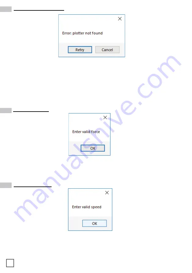
  The plotter might be switched off or not properly connected

Fix:  

Make sure the plotter is turned on and properly connected. 

In case it is turned off, please turn the plotter on and than press the button 2 on 

control panel and wait until the display will show “READY” as status. Then press 

retry on the popup window.

Error: plotter not found

Fix:  

Force must be an integer value from 1 to 31. Try again by typing the correct value.

Enter valid force

Fix:  

Speed must be an integer value from 10 to 600. Try again by typing the correct value

Enter valid speed

37

Summary of Contents for DLF-220L

Page 1: ...USER MANUAL DLF Series Digital Label Finishers this product is certified ...

Page 2: ... in case for a return material If we will receive the system in a non original packaging the warranty will expire automatically IMPORTANT The latest version of the DLF Se ries software is available on our websites afinialabel com or afinialabel co uk ...

Page 3: ...w load the matrix remover slitter How to load the matrix remover core holder How to load the rewinder core holder and set the slitter module How to add or remove blade holder Metal guide alignment DLF CUTTING MANAGER User interface Advanced options Error Messages Black mark detection Cutting file specifications Black mark position into the cutting file and printed artwork Black mark position in th...

Page 4: ...h a screwdriver install the outer discs on the Core Holder for printed roll SYSTEM REQUIREMENTS HOW TO INSTALL OUTER DISC HOW TO INSTALL THE PLOTTER Error Sensor Management dongle usb Camera usb plotter usb usb to pc A Pull the plotter from the packaging and place it on the plate make sure to push the rubber feet into the holes B Plug in the machine and switch it on A B ...

Page 5: ... points to complete the installation 2 Click NEXT 3 Click NEXT 4 Click YES 5 In process 4 HOW TO INSTALL THE CUTTING PLOTTER 6 If required allow installation of application by clicking Yes Click Close The installation is completed a DLF shortcut is displayed on your desktop ...

Page 6: ...folder in the Windows start menu If USB dongle is not installed correctly or un plugged the below error will be shown 5 The grey handle must match with the grey holder and the black handle with the black holder IMPORTANT screws must be face down HOW TO INSTALL THE CORE HOLDER HOW TO LOAD AND OPERATE THE LAMINATION MODULE IMPORTANT If you don t use the lamination roll please cover the sensor with t...

Page 7: ... point you can tighten the core holder When the LEDs on the control board are off the device works on a manual feeding Move the media through the rollers and press the FORWARD button The media will be loaded through the rollers whereas if you push the BACKWARD button the rollers will roll the media backwards 6 Load an empty cardboard core onto the shaft intended for laminate liner rewinding Tighte...

Page 8: ...een LED is on the automatic feeding is activated and operated by the ultrasonic sensor When both yellow and green LEDs are on it indicates the system is in error mode The cause is due to the media or laminate roll is not detected or it is run out If this is not the cause please reset the sensor Turn the screw on the sensor clockwise or counterclockwise This operation has to be done without laminat...

Page 9: ...t damaged or if the tension is too loose the media will not be laminated properly Pull the laminated media underneath the tension arm than pass it through the aluminium rollers the guide can be adjusted preventing the web from rolling Press down the handle on the rear of the plotter Pull the media through the plotter and keep the media edge aligned to the alignment points Just slide set both pinch...

Page 10: ...ark goes in the center position of the blue rectangle area no yes In DISTANCE BETWEEN BLACKMARKS box digit the value relating to the space between top to top black mark 9 HOW TO RUN THE CUT TEST AND START A JOB IMPORTANT WorkingwiththeDLF 220LorDLF 350Lmodels pleaseopen ADVANCED BUTTON click on Settings and uncheck Media Lamination Sensor option then save and close the pop up Press CUT TEST to che...

Page 11: ...to run the blank mode Press OPEN PDF or OPEN LAST JOB to load the cutting file Set the copy mode ON and set 2 as number of copies Click START Check the horizontal position and the gap between the cuts If necessary adjust the offset X and the distance between each cut in STEP BOX Once the cut is set properly select copy mode ON if you desire a preset quantity of copies or OFF if you desire unlimite...

Page 12: ...b from rolling then through the clutch system Close the loading system and the media will be automatically loaded into the clutch path The user can adjust the clutch force thanks to the position of the clutch system Maximum Cluth rewinded roll more tight Minimum Cluth rewinded roll less tight HOW LOAD THE MATRIX REMOVER SLITTER Pull the sides of the black knobs and lift up the clutch system other ...

Page 13: ...ore s width should equal or narrower the width of the finished roll Pull the media through the aluminium rollers and attach the labels to the core using a waste label WARNING Before starting a job always remove completely the waste media from the matrix remover core Tape the matrix uniformly on the cardboard core System operating issues might happen if the above suggestions will not be respected H...

Page 14: ...ter of the labels tighten the thumb screw once the blade is in position Lower position C the blade cut the media OPEN CLOSE B C A The black knobs lock the slitter module in the requested position Screw the thumb knobs to move the blades to the right or to the left A B C Turn ON the Matrix Remover module to rewind and start to split the media than turn OFF 13 ...

Page 15: ...im waste into the waste basket under the hole Press RESUME to start your finishing process Keep out the iron slide bar unscrewing the thumb screw 1 Slide in or out the blade holder Relocate the slide iron bar in its position and rescrew the thumb screw 2 Metal guides can be adjusted in order to prevent the web from rolling HOW TO ADD OR REMOVE A BLADE HOLDER METAL GUIDE ALIGNMENT 14 ...

Page 16: ...1 17 16 2 15 6 7 8 14 10 11 9 12 3 13 4 5 DLF cutting manager DLF CM USER INTERFACE 11 20 18 19 15 ...

Page 17: ...ease or decrease the cut force 10 Increase or decrease the cutting speed 11 Offset adjustment 12 Current camera view 13 Screenshot of the previous black mark detected 14 Preset quantity of labels to be cut on or cut to end manual stop off 15 Number of labels cut 16 Set the gap between black marks top to top 17 Set black mark size 18 Enable blank media mode no black mark printed 19 Set the gap betw...

Page 18: ...s You can find the complete report history file of all the jobs run since cutting manger has been installed through this link YourDocumentsFolder DLF Cutting manager CutHistory txt Clicking SAVE AS your can save wherever you prefer the current work session report Report displays the cuts run since Cutting Manger software has been open Each session report is automatically added and saved to the his...

Page 19: ...the camera reading properly the black mark Press ARROW buttons to move the media until the black mark goes in the center position of the blue rectangle s area If necessary it is possible to slide the camera to left or to right in order to get the black mark centered as much as possible Cutting files Adobe Illustrator or and Corel Draw PDF The artwork file within the cutting shape must be equipped ...

Page 20: ...F FILE You can create this file with Adobe Illustrator or Corel Draw minimum distance from left side of label graphics 4 mm 0 16 black mark can overlap label on bottom Black mark size 4mm x 4mm 0 16 x 0 16 or 2mm x 2mm 0 08 x 0 08 4mm is the minimum distance betwen black mark and label graphics on bottom side Black mark MUST be the leftmost object for round or complex labels black mark can partial...

Page 21: ...lank label feature to cut blank labels without registration mark please follow these steps 1 Import the cut file without registration mark into the software 2 Select the blank label feature from the software and enter the number of copies that you wish to cut 3 Click Start HOW TO CUT BLANK LABELS WARNING Please note that enabling the blank label feature will disable both cut test and Y offset adju...

Page 22: ...WARE 3 When the display shows DEFAULT SETTING press button 1 4 Press button 1 HOW TO RESTORE PLOTTER SETTINGS 1 Turn off the plotter 2 Turn on the plotter while keeping pusched the UP arrow on the panel 5 Press button 1 6 In process 7 When the display shows SET DEFAULT COMPLETE turn off the plotter 8 Turn on the plotter and Choose the language and press enter ...

Page 23: ...then enter 10 Press button 2 11 Wait until on the display appears READY 12 Press PAUSE MENU button 13 Go to page 2 by using the arrows on plotter s panel 14 Press button 1 15 Press button 1 and then Enter 16 Restart the plotter and press button 2 ...

Page 24: ...ends on the job in process WHEN AND HOW TO REDUCE THE PLOTTER FEEDING SPEED 17 Wait until on the display appears READY 18 Open the Cutting manager and click on Advanced and then select Init cutter 19 Wait until Init cutter completed will be shown in the status bar Plotter display will show LABEL MEDIA as status 23 ...

Page 25: ...For DLF 220L DLF 350L turn ON the unwinder when you procede to the sensor calibration 1 Raise the tension arm to the fullest spring has to extend completely 2 Take a paper clip and insert it into the little hole located next to the OFF ON switch and push it down for 5 seconds The yellow led will light up 3 Release the tension arm The yellow led will stay on 4 Push again the paper clip down into th...

Page 26: ...350L MODELS MATRIX REMOVER SLITTER MODULE WARNING If what pictured above is not happening please press the button on circuit board untill the yellow led flashes After it flashes for 5 times release the button and perform a new test ULTRASONIC TENSION CONTROLLER ULTRASONIC TENSION CONTROLLER 25 ...

Page 27: ...to install the roller Unscrew the 10 screws on the matrix remover module 1 Position the matrix remover roller onto the matrix remover module and secure it properly with the 10 screws 2 HOW TO USED THE O RING ON THE MATRIX ROLLER The o rings of the matrix remover roller are used to facilitate the removal of your matrix from the labels Place one or more o rings depends on the width of the label at t...

Page 28: ...blade Plunger cap blue Hole Adjust the blade length by turning the blade length adjustment knob Turn the knob in direction A to extend the blade or in direction B to retract the blade When the knob is turned by one scale unit the blade moves approximately 0 1 mm One full turn of the knob moves the blade approximately 0 5 mm WARNING It may result in damaging the cutter blade or the cutting mat if t...

Page 29: ...the screw When removing the tool turn it counterclockwise to remove the tool Removing the tool Bracket to hold tool Tool holder Tool holder Bracket to hold tool TOP Bracket to hold tool Flange Tool holder Tool holder 1 Backward Half cutting Plotting Pen Tool holder 2 Forward Using cutting SUPPLEMENT When using with half cutting and plotter pen set the seal in Tool Holder 1 backward and when using ...

Page 30: ... hole provided in the plunger cap 5 With the blade inserted into the plunger cap screw on the plunger from above 6 Fix the plunger cap by turning it clockwise HOW TO REPLACE THE KNIFE See page 27 for the structure of the cutter plunger ATTENTION In order to preserve the lifespan of the plotter knife and not to wear it out quickly it is best to properly calibrate the knife exposure and cut force de...

Page 31: ... adhesives left on the cutting base Please clean the cutting mat base before installing the cutting mat Installing the cutting mat with the remaining adhesive may affect cut quality 2 Installing the cutting mat Fit the cutting mat with the front cutting base grooves fig 3 and attach it from the location shown by the arrow A fig 1 while peeling off the release paper CAUTION Please turn off the powe...

Page 32: ...NY OF OUR DLF UNITS PLEASE FOLLOW TROUBLESHOOTING STEPS BELOW Yellow and Green LED s simultaneously on lamination control board Applies to all DLF models The media sensor is used to detect the presence of the media The LED on this sensor should always be ON after the media has been loaded properly through all the guides this would also indicate that the sensor is in good working condition Things t...

Page 33: ... when the lamination roll is detected and turn ON when lamination roll has run out Lamination Sensor Problem If the media is not aligned properly after running a couple of jobs Cause This problem occurs for a couple of reasons The primary reason would be that the tension force on the on the rubber roller assembly media core and the lamination core If using lamination are all out of sync and needs ...

Page 34: ...he cut force in DLF CM while decreasing the blade exposure until the unit provides satisfactory results or you can also decrease the cut force and increase the blade exposure until it produces a perfect cut Adjust both accordingly until the correct cut setting has been achieved If the plotter is cutting through the media this can be fixed by decreasing both the cut force and blade exposure to fact...

Page 35: ...that the pinch rollers are aligned properly with the plotter s grips Plotter error E05004 Hardware Realign Push Rollers Confirm Problem The plotter displays an error E01019 Hardware Y Position Alarm Power off then on Cause This error occurs when the blade tray was moved from side to side by the user after loading the media onto the plotter and with the rear plotter lever in the up position Problem...

Page 36: ...e front and back of the plotter This is done with the plotter s rear handle in the down position make sure to position the plotter s camera over the blackmark in order to centered marker as much as possible on the software camera preview Cutting Manager error Black mark not found Problem After starting a job in DLF CM you get an error Black mark not found Cause When both the yellow and green LEDs ...

Page 37: ... Error load the media Cause You launched the Cutting Manager while the plotter s lever was down Fix Plug in the dongle correctly and click retry cancel choice will close the Cutting Manager Dongle not found Cause Sensors might be not plugged in correctly or turned off Fix Check if sensors are powered up and plugged correctly into the black sensor box Then Retry If you do not keep activated the sen...

Page 38: ...r on and than press the button 2 on control panel and wait until the display will show READY as status Then press retry on the popup window Error plotter not found Fix Force must be an integer value from 1 to 31 Try again by typing the correct value Enter valid force Fix Speed must be an integer value from 10 to 600 Try again by typing the correct value Enter valid speed 37 ...

Page 39: ... value you can see coordinates on plotter s display when you move the media with arrows Keep in mind also the offset influences the starting position of the cut So if you start the cut at Y coordinates 0 while you have an offset Y value of 10 you will still get this error This error might happens when the media has been just loaded Fix Move to the next black mark If it is not enough forward until ...

Page 40: ... positive Y value shown on the plotter s display Cause You will get this error when you try to open the last job when you run Cutting Manager for the first time after the installation Fix Choose your file through Open PDF Last job not found Fix In this case you might need to replace the comma with a dot or vice versa Make sure to check replace comma or dot for Delta Y and X values into Advanced Se...

Page 41: ... the camera is working correctly put something under the lens and make sure it is shown on the Cemera preview as well If not unplug and plug in back the camera usb cable and restart both plotter and the Cutting Manager If the camera is working now but the plotter still does not execute any cut refer to ERROR 1 instruction not recognised and follow the instructions Check if camera restarts and try ...

Reviews:

Related manuals for DLF-220L