


aesys
Standard Sign System
Maintenance Manual
ASMM2010
Page
37
Version 1.0 • April 2011
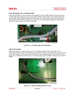
The sign housings have holes for power and data cables as well as holes for mounting brackets (refer to
Figure 39). Wherever cables exit the housing, rubber gaskets are always used to protect the internal
components.
Figure 39
— Sign Bracket Mounting Holes
Referring to Figure 40, the figure illustrates the standard sign system general power and data circuits.
Depending upon each unique installation, circuit may be composed of a different number of cables of
different lengths. Although there are considerable variations in installations, the power and data each
contain the same basic components that perform the same functions from application to application.
Figure 40
— Standard Sign System General System Diagram
ASMM2010-003.CDR
CCU to display panel data circuit wiring harness
Power supply wiring harnesses
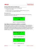
Emergency/Panic
Alarm Switch
Summary of Contents for KC640
Page 1: ...Standard Sign System Maintenance Manual Publication Number ASMM2010 Version 1 0 April 2011...
Page 83: ...aesys Standard Sign System Maintenance Manual ASMM2010 Page 83 Version 1 0 April 2011 NOTES...
Page 84: ...aesys Standard Sign System Maintenance Manual ASMM2010 Page 84 Version 1 0 April 2011 NOTES...


