aesys
Standard Sign System
Maintenance Manual
ASMM2010
Page
54
Version 1.0 • April 2011
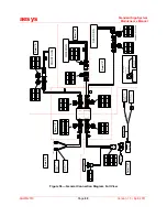
Figure 50
— Sign Electrical/Cable Harness Interconnection Block Diagram
Table K
— Guide to Electrical Information Illustrations and Parts List
Figure Number or Initial Figure Number or Table and Description
Pages
Figure 50
— Sign Electrical/Cable Harness Interconnection Block Diagram
Above
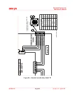
Figure 51
— Electrical Schematic Electrical Connections, Full View and Detailed Views
55 - 59
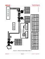
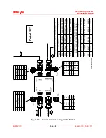
Figure 56
— General Connection Diagram, Full View and Detailed Views
60 - 66
Figure 63
— Standard Junction Box, Full View and Detailed Views
67 - 71
Figure 68
— Main Power Cable
72
Figure 69
— F02 Front Sign Extension Cable
73
Figure 70
— Front Sign
74
Figure 71
— S02 Side Sign and Rear Sign Extension Cable
75
Figure 72
— Side Sign
76
Figure 73
— Rear Sign
77
Figure 74
— C01 KC640 Data and Power Cable
78
Figure 75
— Alarm Cable Hook-up Wire
79
Figure 76
— Adaptor DB9 Male/Female
80
Table L
— Standard Parts List
81
FRONT SIGN
REAR SIGN
SIDE SIGN
RS-485 (SIGN)
CCU
RS-485 (J1708)
J1708
ON BOARD COMPUTER
ASMM2010-004.CDR
Summary of Contents for KC640
Page 1: ...Standard Sign System Maintenance Manual Publication Number ASMM2010 Version 1 0 April 2011...
Page 83: ...aesys Standard Sign System Maintenance Manual ASMM2010 Page 83 Version 1 0 April 2011 NOTES...
Page 84: ...aesys Standard Sign System Maintenance Manual ASMM2010 Page 84 Version 1 0 April 2011 NOTES...


