background image


29


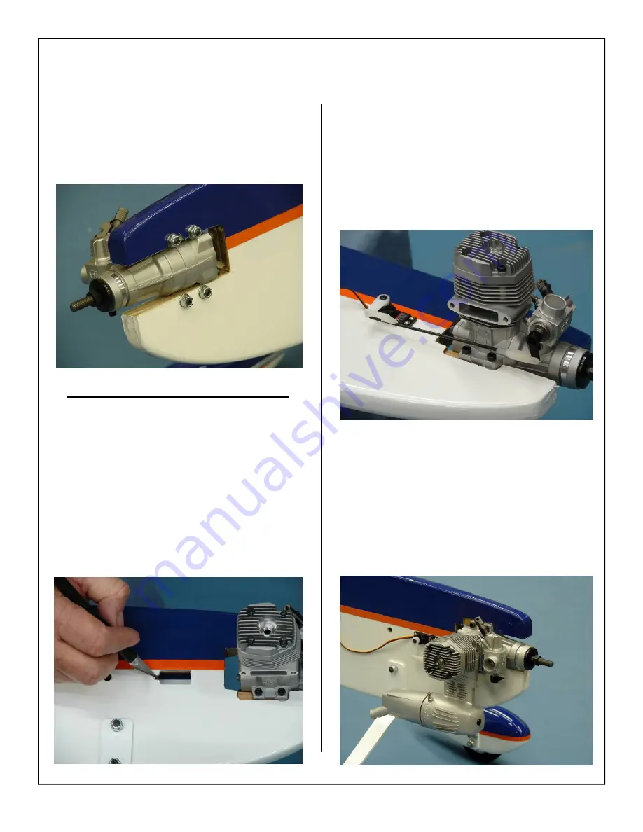
6.  Place engine between mounting rails and allow 

all four bolts to pass through. Install flat washer 
and 6-32 lock nuts onto mounting bolts and 
tighten them evenly. Ensure that the wood does 
not crush as the bolts are tightened.  


2 Stroke Throttle Servo Installation  

 
1.  Remove the covering from the 

LOWER

 throttle 

servo mount using a sharp hobby knife as 
shown.  


Note: 

Two throttle servo mounting locations have 


   been provided, if using a 4 stroke engine     


   please skip to step #1 on page 30 

2.  Install the throttle servo using the servo screws 

provided with the servo.  

 
3.  Install throttle servo linkage as shown below.  

4.  Finished 2 stroke engine  installation shown be-

low.  

Summary of Contents for ProX260 ARF-QB

Page 1: ...1 46 60 ProX260 ARF QB 60 90 ProX260 ARF QB Quick Build ASSEMBLY MANUAL AEROWORKS 4903 Nome Street Denver CO 80239 Phone 303 371 4222 Fax 303 371 4320 E mail info aero works net...

Page 2: ...b and Elevator Assembly 18 Vertical Fin Rudder and 40 60 Tail Wheel Installation 20 Main Landing Gear Wheel Pants Assembly 21 Tail Wheel Assembly 60 90 Size Only 24 Elevator Rudder Servo Installation...

Page 3: ...eroworks manufacturing guarantees this kit to be free from defects in both material and workmanship at the date of purchase This warranty does not cover any component parts damaged by use or modificat...

Page 4: ...g the assembly of your new ProX260 ARF QB Inventory and inspect all parts and hardware for any imper fections or damage Notify Aeroworks immediately if there are missing or damaged parts INTENDED USE...

Page 5: ...g with Aileron covered Pre drilled for the mounting of the control horns Pre cut hole Covered in bottom of wing for the servo extension Aileron is in place with 5 CA hinges not glued Servo Hatch Cover...

Page 6: ...n bracket and tail wheel mounted 3 T2 6x12mm Phillip Head Screws for tail wheel assembly mounting 4 4 150mm long Pushrod with M2 thread at one end with metal clevis 5 Nylon Half Clevis 1 300mm long Pu...

Page 7: ...mounting of the control horns Pre cut hole Covered in bottom of wing for the servo extension Aileron is in place with 5 CA hinges not glued Servo Hatch Cover in place with 2 nylon small latch hatch 2...

Page 8: ...40x102mm Pushrod with thread at both ends 8 Metal Clevis 1 Nylon Half Clevis 1 300mm long Pushrod with M2 thread at one end with Nylon clevis 9 Glow Fuel Line for fitting over clevis 4 Nylon Control...

Page 9: ...tch with charge jack Tools Allen wrenches US and Metric Dremel cutting disc and sanding drum tool Electric drill and selection of bits Razor saw Flat head screwdriver Hobby heat gun Hobby iron and cov...

Page 10: ...with charge jack Tools Allen wrenches US and Metric Dremel cutting disc and sanding drum tool Electric drill and selection of bits Razor saw Flat head screwdriver Hobby heat gun Hobby iron and coverin...

Page 11: ...tly apply pressure and rub in the covering If any bubbles occur your iron may be to hot Reduce heat and work slowly 3 If bubbles persist use a small pin to punch holes in the bubble to relieve trapped...

Page 12: ...to ensure all edges seams and color overlaps are securely sealed IMPORTANT It is the purchaser user responsibility to check the covering seams and overlaps for se curity and a good seal Aeroworks is...

Page 13: ...all 5 CA hinges have been placed in the wing slide the aileron onto the hinges Once again it is very important that the hinge stay straight 3 Use a straight edge to make sure that the aileron sits fl...

Page 14: ...through the top of the wing when installed 6 Install servo in the servo bay inside the wing Ensure that the output shaft is towards the trail ing edge of the wing 7 Ensure the output shaft is centered...

Page 15: ...o install the 2 con trol horn mounting bolts through the aileron 4 Thread the two mounting bolts into the control horn base plate on top of the aileron Be careful not to over tighten as this could cru...

Page 16: ...eepers 3 At the location marked in the previous step make a 90 degree bend in the pushrod Remove the excess rod with a pair of wire cutters Install the pushrod through the servo arm and into the ny lo...

Page 17: ...clevis to keep it secure 60 90 Pushrod Assembly 1 Gather the following items for the 60 90 size model shown below 2 4 40 Pushrods 4 4 40 threaded metal R C links 4 4 40 Lock nuts 2 Final servo install...

Page 18: ...t is centered left to right in the fuse and is pushed all the way forward Measure from the wingtips to the corner of each side of the stab adjust the stab until these distances are equal This ensures...

Page 19: ...in fuse and double check align ment Allow the Epoxy to dry before continuing Note Clean off excess epoxy using rubbing alcohol Note Make certain the stab is pushed all the way forward 8 Pin each CA h...

Page 20: ...tinuing Note Clean off excess epoxy using rubbing alcohol 46 60 SIZE ONLY 3 Use 30minute epoxy to secure the steering arm inside the precut slot in the rudder as shown Note If building the 60 90 size...

Page 21: ...e landing gear parts as shown below 2 Aluminum Landing gear struts 2 8 32 mounting bolts 4 Flat washers 2 8 32 Lock nuts 2 Wheel pants 4 4 40 mounting bolts 2 Wheels 2 Axle assemblies 4 Wheel collars...

Page 22: ...the flat sides of the axle bolt vertical and snug the lock nut against the landing gear strut Note Do not tighten securely yet 6 Align the wheel pant slot over the axle bolt as shown Slide the wheel...

Page 23: ...collar Use blue Loctite on the wheel collar set screw before final tightening 10 Final installation of wheel pant with two mount ing bolts Note Make sure wheel turns freely without binding or rubbing...

Page 24: ...mounting holes at bottom of rudder 2 Apply a drop of thick CA to the tiller arm mounting screws before inserting in the pre drilled holes 3 Mount the tail wheel steering tiller using two wood screws 4...

Page 25: ...25 5 Attach the rudder steering springs to the rudder tiller arm and tail wheel steering arm 6 Tail wheel installation is now complete...

Page 26: ...holding the pull string from inside the fuse as shown 2 Install the servos using the servo screws pro vided with the servo 3 Install the pushrods using the same installation method as shown for the wi...

Page 27: ...the guide string through the fuse be careful to not pull to hard and cause the string to break or come undone 7 Use masking tape to secure the string to the ex tensions This will also help the extensi...

Page 28: ...bit to drill the engine mounting holes into the engine mount Note Drill the engine mounting holes as straight as possible 2 STROKE ENGINE AND THROTTLE SERVO INSTALLATION 3 Gather the items shown belo...

Page 29: ...2 Stroke Throttle Servo Installation 1 Remove the covering from the LOWER throttle servo mount using a sharp hobby knife as shown Note Two throttle servo mounting locations have been provided if using...

Page 30: ...servo mount using a sharp hobby knife as shown Note Two throttle servo mounting locations have been provided if using a 2 stroke motor please skip to step 1 on page 29 2 Install the throttle servo us...

Page 31: ...the fuse just in front of the wing as shown below Mark the location of the tank mounting eyelets using a black felt tip pen 3 Install the 4 threaded eyelets as shown below Note Thick CA may be used on...

Page 32: ...32 5 Install the fuel tank using the provided nylon ties and foam pad as shown below 6 Install the fuel lines to the carburetor and muf fler as shown...

Page 33: ...d run it out through the precut hole in the wing Attach the servo lead to the extension and secure with wire Note If the wings will be removed frequently an Aeroworks Safety Clip is recommended to sec...

Page 34: ...may vary from photos below Note Clean surface and tighten all covering before any decals are applied Decal installation 2 Factory placement of decals shown 4 Factory placement of decals shown 3 Facto...

Page 35: ...fuse side and into the wing root blind nut Tighten snugly but do not over tighten and crack the fuse or wing root wood PRE FLIGHT PREPARATION 2 Mount the Side Force Generator using two 4 40 mounting...

Page 36: ...that is fine to start with After you are comfort able adjust the CG to suit your flying style in small steps especially when shifting the CG to ward the tail Move the battery or add small stick on we...

Page 37: ...e elevator throw in inches 4 Gather the Rudder Throw Meter Supplied and scotch tape 5 Slide the throw meter under the rudder boost tab Use scotch tape to secure the throw meter to the vertical fin 6 D...

Page 38: ...Prop up the tail of the aircraft until the fuselage is parallel to the table top Throw meter is available from Aeroworks 8 Use the widest part of the aileron to measure the aileron throw in degrees 9...

Page 39: ...rates and 60 expo on 3D rates as a starting point You a can adjust from there to suit your own flying style Control Throw Deflection Table 60 90 ProX260 Low Rate High Rate Aileron 2 or 20 up 3 or 30 u...

Page 40: ...collars and clevis keepers are tight and secure Covering Check all covering and seams are sealed and secure Radio Check trims set to neutral and controls centered Check rate and condition switches se...

Reviews: