background image


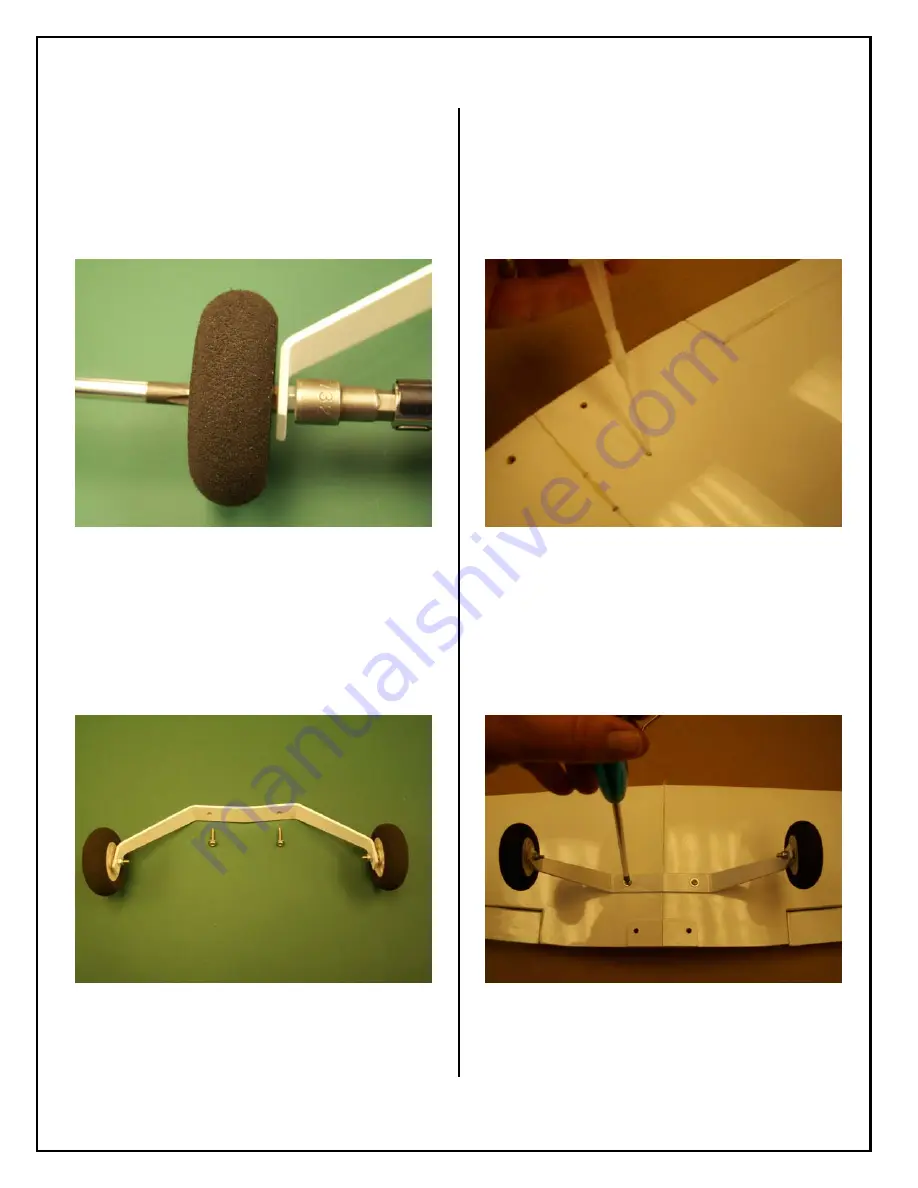
21.  Insert the axle bolt through the main landing gear 

strut and screw the nylon lock nut tightly against 
the main landing gear strut.  Keep the axle bolt 
from turning with a Phillips head screwdriver.  
Check that the wheel freely rotates without 
excess play or wobble.  Adjust bolt and nuts as 
necessary. 


22. Main landing gear assembly is now complete.  

Locate the self-tapping screws for mounting to 
the wing. 


23. Place a drop of thin CA into the predrilled 

landing gear mounting holes to harden the wood 
mount.   


24.  Mount the landing gear to the bottom of the wing 

using two self-tapping screws.  Do not over 
tighten and strip the threads in the plywood wing 
mounts. 


14 


Summary of Contents for BD-5B ELECTRIC ARF

Page 1: ...BD 5B ELECTRIC ARF ASSEMBLY MANUAL 1...

Page 2: ...t Information 3 Introduction 4 Kit Contents 5 Items needed to complete 7 Covering 8 Wing Assembly 9 Stab and Elevator Assembly 17 Rudder Nose Gear Servos and Motor Installation 21 Radio Installation 2...

Page 3: ...you will ever build and fly We provide you with the highest quality and performance possible We wish you great success in the assembly and flying of your new Aeroworks BD 5B Electric ARF WARNING An R...

Page 4: ...and inspect all parts and hardware for imperfections or damage Notify AEROWORKS immediately if there are missing or damaged parts IMPORTANT Please read through the assembly manual carefully before st...

Page 5: ...control horn installed Wing bolt holes pre drilled 3 Horizontal Stabilizer and Elevator covered Elevator in place with CA hinges not glued 5 Control horn holes pre drilled 4 Fuselage assembled and cov...

Page 6: ...g tiller with set screw 2 wheel collars 6 Control system parts 2 wire aileron pushrods 4 pushrod easy links 1 nylon elevator control horn 7 Misc assembly parts Plywood dihedral brace Plywood aileron s...

Page 7: ...1 x elevator mini servo Recommend Hitec HS 55 1 x 6 servo extension 7 Tools Modeling knife Electric drill and selection of bits Phillips screwdriver Needle nose pliers Allen wrenches US and Metric Sc...

Page 8: ...g you will be rewarded with a long lasting beautifully covered model 2 Using your covering iron with a soft sock gently apply pressure and rub in the covering If any bubbles occur your iron may be to...

Page 9: ...Then reinstall the aileron onto the CA hinges and aileron torque rod Press the aileron against the trailing edge of the wing and the T pins as shown below Remove any excess epoxy with alcohol wipes 3...

Page 10: ...poxy Use masking tape to hold the wing panels tightly together until epoxy cures Use alcohol wipes to wipe any excess epoxy smears or finger prints from the covering material before it cures 6 After e...

Page 11: ...enter joint of the wing halves 10 Attach two easy links to the aileron servo arm as shown Use a 2mm or 5 64 bit to drill out the servo arm holes if necessary Do not over tighten the nut The easy link...

Page 12: ...ron servo mount 15 Mount the aileron servo using servo mounting screws 16 Tape the trailing edge of each aileron to the trailing edge of the wing Rotate the aileron servo output arm parallel to the tr...

Page 13: ...ervo installation is now complete 19 Gather the main landing gear parts as shown below Note that each axle bolt has a regular nut and a nylon lock nut 20 Insert the axle bolt through the wheel and scr...

Page 14: ...otates without excess play or wobble Adjust bolt and nuts as necessary 22 Main landing gear assembly is now complete Locate the self tapping screws for mounting to the wing 23 Place a drop of thin CA...

Page 15: ...fe to cut the dowel relief out of the plastic belly pan 27 Trial fit the belly pan on the bottom of the wing and make sure there is no interference from the wing dowel to the belly pan 28 Install the...

Page 16: ...t inside the line where the edges of the belly pan will contact the bottom of the wing Clean the area with alcohol to give a good CA glue bond 31 Align the belly pan on the wing along the pencil lines...

Page 17: ...rows Next place 3 4 drops of thin CA on each side of all hinges Do not over soak the CA hinges Glue may run out and cause binding 3 Insert the nylon elevator control horn into bottom of the elevator t...

Page 18: ...run out and bond to the covering material 7 After the CA has cured use wire cutters to clip the prongs flush with the top of the elevator surface Apply a drop of thin CA to each prong to bond the con...

Page 19: ...cuff the surface of the covering material just inside the line where the edges of the fuse will contact the surface of the stab Clean the area with alcohol to remove the ink lines and give good CA glu...

Page 20: ...13 Install the wire elevator pushrod into the control horn and attach the nylon pushrod keeper as shown 20 The stab and elevator installation is now complete...

Page 21: ...edge Then reinstall the rudder onto the CA hinges and the rudder torque rod Press the rudder against the trailing edge of the fin and the T pins as shown below 15 Remove the T pins Allow enough hinge...

Page 22: ...slop in the nose gear mounting plate 19 Attach the pre bent nose gear steering pushrod clevis to the nose gear steering tiller as shown below 20 Insert the nose gear steering pushrod up into the right...

Page 23: ...th Lock Tite or a small drop of CA glue 24 Insert the elevator pushrod thru the elevator easy link and then install the elevator servo with servo screws Insert the rudder pushrod and the nose gear ste...

Page 24: ...der and nose wheel are both centered when the servo arm is at the centered position Remove the tape 27 Use wire cutters to cut off the excess elevator rudder and nose wheel steering pushrod wire Leave...

Page 25: ...hrough the fuse toward the nose 32 Insert the motor shaft through the center hole in aft fuse motor mount and press the motor rearward against motor mount Rotate the motor to align the mounting holes...

Page 26: ...t Space the prop shaft on the motor shaft so that the spinner back plate has clearance from the aft fuse motor mount former 36 Install the prop prop washer and prop nut on the prop shaft Tighten secur...

Page 27: ...vering material patch 40 Place the covering material patch over the rudder control horn inspection hole on the left side of the fuse and iron in place 41 Use the iron to shrink the patch to cover the...

Page 28: ...the speed controller under the battery tray and mount with double sided foam tape 3 We chose to mount the speed control arming switch inside to the forward right side of the servo tray The switch is...

Page 29: ...ect channels of the receiver 8 Slide the receiver antenna under the servo tray to the aft section of the fuse Carefully tuck the servo wires under the servo tray and mount the receiver to the fuse flo...

Page 30: ...to secure the antenna wire to the bottom of the wing or fuse as desired Route the aileron servo extension through the right side round hole in the fuse former to connect to the aileron servo wire when...

Page 31: ...that is fine to start with After you are comfortable adjust the CG to suit your flying style in small steps especially when shifting the CG toward the tail Move the battery or add small stick on weigh...

Page 32: ...ection Table Low Rate High Rate Aileron 3 16 or 15 up 5 16 or 20 up 3 16 or 15 down 5 16 or 20 down Rudder 3 16 or 14 left 5 16 or 20 left 3 16 or 14 right 5 16 or 20 right Elevator 3 8 or 15 up 5 8 o...

Page 33: ...xperienced flyers have lost airplanes due to reversed ailerons Right roll is right up left down Left roll is left up right down 26 Batteries Ensure the transmitter receiver motor batteries are fully c...

Page 34: ...ne if full deflections are used at high speeds When flying at high speed use caution using full control deflections to avoid overstressing the airplane The BD 5B is capable of gentle and stable slow f...

Reviews: