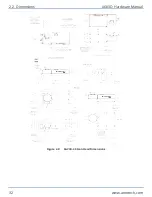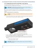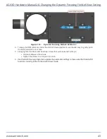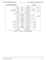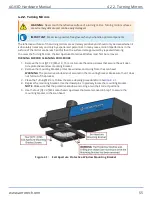
Figure 2-10:
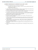
Dynamic Focusing Module Reference
4. To keep the DFM referenced after the Field of View adjustment, use the allen key to gently push
the DFM towards the rear face.
5. Slowly tighten the M4 socket head cap screws that were loosened in Step 2.
l
Alternate between the screws.
l
Tighten the screws to a torque of 30 in·lb.
6. Use the AGV3D setup programs to update the parameter settings to make sure that the AGV3D
functions correctly. Refer to the AGV3D User Guide.
AGV3D Hardware Manual 2.8. Changing the Dynamic Focusing Field-of-View Setting
www.aerotech.com
43
Summary of Contents for AGV3D Series
Page 1: ...Revision 2 00 AGV3D Three Axis Laser Scan Head HARDWARE MANUAL...
Page 6: ...This page intentionally left blank List of Tables AGV3D Hardware Manual 6 www aerotech com...
Page 12: ...This page intentionally left blank Laser Shutter AGV3D Hardware Manual 12 www aerotech com...
Page 16: ...Figure 1 2 Standard AGV3D Chapter 1 Overview AGV3D Hardware Manual 16 www aerotech com...


