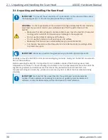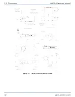
Figure 2-5:
Mounting Point Locations
Table 2-1:
Mounting Hardware Specifications
Location
Quantity
Screw Size
Right Side
4
M6x1, 9 mm LG
Rear Side
4
M6x1, 9 mm LG
Bottom
4
M6x1, 9 mm LG
Table 2-2:
Mounting Specifications
Specification
Parallelism to Workpiece
50 µm over 100 mm
Mounting Surface Flatness
25 µm over 305 mm
2.4. Securing the Scan Head to the Mounting Surface
AGV3D Hardware Manual
36
www.aerotech.com
Summary of Contents for AGV3D Series
Page 1: ...Revision 2 00 AGV3D Three Axis Laser Scan Head HARDWARE MANUAL...
Page 6: ...This page intentionally left blank List of Tables AGV3D Hardware Manual 6 www aerotech com...
Page 12: ...This page intentionally left blank Laser Shutter AGV3D Hardware Manual 12 www aerotech com...
Page 16: ...Figure 1 2 Standard AGV3D Chapter 1 Overview AGV3D Hardware Manual 16 www aerotech com...

