AERMEC NRL 0280 Installation Manual Download Page 47

47

18.01._5280107_02

NRL 0280-0750 °-L / A-E

EN

CONTROL AND COMMISSIONING

PREPARATION FOR COMMISSIONING

Please note that, on request by the Aermec customer or 

the legiti mate owner of the machine, the units in this se-

ries can be started up by the AERMEC Aft er-Sales Service 

in your area (valid only on Italian territory).

The  start  of  operati on  must  be  scheduled  in  advance 

based on the frame regarding the realisati on of the sys-

tem. Prior to the interventi on, all other works (electrical 

and hydraulic connecti ons, priming and bleeding of air 

from the system) must have been completed.

START - UP

PRELIMINARY OPERATIONS TO BE PERFOR-

MED WITH NO VOLTAGE PRESENT

Control:

1. 

All safety conditi ons have been respected.

2. 

The unit is correctly fi xed to the support 

surface.

3. 

The minimum technical spaces have been 

respected.

4. 

That the main power supply cables have  

appropriate cross-secti on, which can support 

the total absorpti on of the unit 

(see electric 

data secti ons)

 and that the unit has been duly 

connected to earth. 

5. 

That all the electrical connecti ons have been 

made correctly and all the clamps adequately 

ti ghtened.


THE FOLLOWING OPERATIONS ARE TO BE CAR-

RIED OUT WHEN THE UNIT IS LIVE.

1. 

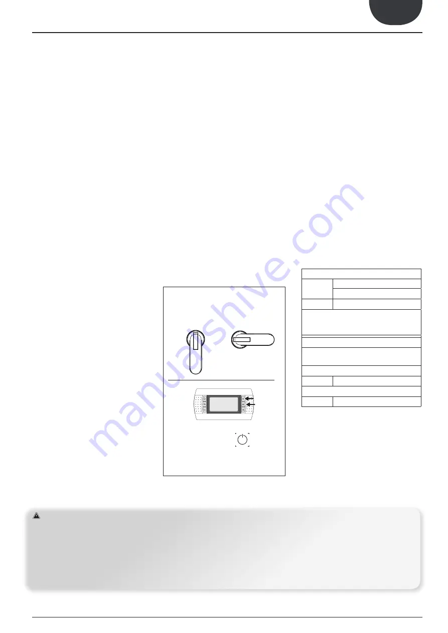
Supply power to the unit by turning the master 

switch to the ON position; see (fig1.) The display 

will switch on a few seconds after voltage has 

been supplied; check that the operating status 

is on OFF (OFF BY KEY B on lower side of the 

display). 

2. 

Check with a tester that the value of the supply 

voltage to the phases:  single-phase – three-phase 

is within the present limits:  ±10% (230V ±10% - 

400V ±10%), and that the unbalance between the 

phases is not more than 3% (only for three-phase 

models) 

3. 

Check that the connections made by the installer 

are in compliance with the documentation.

4. 

Verify that the compressor sump resistance/s 

is/are operating by measuring the increase in 

temperature of the oil pan. The resistance/s must 

function for at least 12 hours before start-up of 

the compressor and in any event, the tempera-

ture of the oil pan must be 10-15°C higher than 

room temperature.

HYDRAULIC CIRCUIT

1. 

Check that all hydraulic connections are made 

correctly, that the plate indications are complied 

with and that a mechanical filter has been 

installed at the evaporator inlet 

(mandatory 

component for warranty to be valid).

2. 

Make sure that the circulation pump/s is/are  

operating and that the water flow rate is    

sufficient to close the flow switch contact.

3. 

Check the water flow rate, measuring the 

pressure difference between evaporator inlet 

and outlet and calculate the flow rate using the 

evaporator pressure drop diagram present in 

the technical manual

 (available on the software 

selection and on the website www.aermec.com

4. 

Check correct operation of the flow meters, if 

installed (or supplied with the unit or by the 

installer – see  the chapter of hydraulic circuit to 

know the components supplied with the unit): 

• 

Flow switch/Pressure switch:  

on closing the 

cut-off valve at the heat exchanger outlet, the unit 

must display the block. Finally, open the valve and 

rearm the block.

MACHINE COMMISSIONING

The unit can be used aft er all of the above-menti oned 

controls have been performed.

- Close the electric control board hatch.

- Positi on the appliance master switch at ON

-  Starting the unit

WITH THE MACHINE ON, CHECK

COOLING CIRCUIT


CHECK:

-  That the compressor input current is lower than the 

maximum indicated in the technical data table.

-  That in models with three-phase power supply, the 

compressor noise level is not abnormal. If this is the 

case, invert a phase.

-  That the voltage value lies within the pre-fixed limits 

and that unbalance between the three phases (three-

phase power supply) is not above 3%.

-  The presence of any refrigerant GAS leaks, parti cu-

larly in correspondence with the manometers pres-

sure transducers and pressure switches pressure 

points  (vibrati ons  during  transportati on  may  have 

loosened the fi tti  ngs).

-  Overheating                                                                                               

  Comparing the temperature read using a contact 

thermostat positioned on the compressor intake with 

the temperature shown on the low pressure manom-

eter (saturation temperature  

corresponding  to 

the  evaporation  pressure).  The  difference  between 

these two temperatures gives the  

over-

heating value. Optimal values are between 4 and 8°C.

-  Pressing line temperature. If the subcooling and 

overheating values are regular, the temperature 

measured in the pressing line pipe at the outlet of 

the compressor must be 30/40°C above the conden-

sation temperature.

Operati ng features (Factory set) 

7°C / ∆t=5°C

Cooling Only
Heat Pump in Cooling Mode

45°C / ∆t=5°C Heat Pump in Heati ng Mode

If the unit power supply is restored aft er a tempo-

rary interrupti on, the mode set will be kept in the 

memory.

Compressor Start-Up Delay

Two functi ons have been set-up to prevent com-

pressor start-ups that are too close.
Minimum time from last switch-off 

60 seconds

in Cooling Mode

Minimum time from last switch-on 

300 seconds

in Heati ng mode

ATTENTION

1)

Commissioning must be performed with standard settings. 

Only when the inspection has been completed can the functio-
ning Set Point values by changed. 
Before start-up, power the unit for at least 12-24 hours, posi-
tioning the protection magnet circuit breaker switch and the 
door lock isolating switch at ON.
Make sure that the control panel is off in order to allow the 
compressor oil sump to heat.

2)


We recommend to envision a machine book (not

supplied,  but  the  user’s  responsibility),  which  allows  to  keep 

track of the interventions performed on the unit.
In this way it will be easy to suitably organise the interventions 
making research and the prevention of any
machine breakdowns easier. Use the date to record date, type

of intervention made (routine maintenance, inspection or re-
pairs), description of the intervention,

measures actuated.

3)

It is forbidden to LOAD the cooling circuit with a refrigerant 

different to that indicated. Using a different refrigerant gas can 
cause serious damage to the unit.

ON

ON

OFF

OFF

SELECT MENÙ 

ON/OFF

16. 

CONTROL AND COMMIS

Summary of Contents for NRL 0280

Page 1: ...s Scroll Compressors Compact High Efficiency Installation Manual Installation Manual EN 18 01 _5280107_02 Aermec participate in the EUROVENT program the products are present on the site www eurovent c...

Page 2: ...ars of experience and in depth engineering research and it is built using top quality materials and advanced technologies In addition the CE mark guarantees that our appliances fully comply with the r...

Page 3: ...tem loading 30 7 System emptyng 30 8 System draining 31 9 Percentage weight distribution 34 10 Electric connections 37 11 Electronic control pCO5 40 12 User interface pGD1 42 13 Start up procedure 43...

Page 4: ...N 60335 2 40 A13 2012 CEI EN 55014 2 2016 La presente dichiarazione di conformit rilasciata sotto la responsabilit esclusiva del fabbricante This declaration of conformity has been released under the...

Page 5: ...Campo d impiego Modello Model Mod le Modell Modelo Recupero di calore Heat recovery R cup rateursdechaleur W rmer ckgewinnung Recuperadores de calor Versione Version Version Ausf hrung Version NRL 28...

Page 6: ...ntation is compiled in accordance with part B of Annex VII this documentation or part of it will be transmitted by mail in response to a reasoned request by the national authorities La documentation t...

Page 7: ...with the heat pump as dangerous situations can be created and the manufacturer will not be liable for any damage caused The warranty shall be become null and void if the above mentioned indications ar...

Page 8: ...wing 1 The support surface must be capable of supporting the unit weight 2 The safety distances between the units and other appliances or structures must be scrupulously respected 3 The unit must be i...

Page 9: ...ANTIVIBRANT POSITION mm NRL_0280 0330 L 6 1 6 1 6 1 6 1 2050 0 0 2 0 0 2 2050 0 0 2 0 0 2 2510 mm 1160 mm 150 mm 420 1610 420 40 40 20 1060 20 1100mm 2450mm 1606mm DIMENSIONS mm PUNTI DI SOLLEVAMENTO...

Page 10: ...50 L NRL_0280 E 6 1 6 1 6 1 6 1 2050 0 0 2 0 0 2 2050 0 0 2 0 0 2 1606mm 2450mm 1100mm 2510 mm 1160 mm 150 mm 420 1610 420 40 40 20 1060 20 DIMENSIONS mm PUNTI DI SOLLEVAMENTO mm POSITION OF ANTIVIBRA...

Page 11: ...RL_0300 E 6 1 6 1 6 1 6 1 0 0 2 0 0 2 2550 2550 0 0 2 0 0 2 1606mm 2950mm 1100mm 3010 mm 1160 mm 150 mm 395 1960 602 40 40 20 1060 20 DIMENSIONS mm PUNTI DI SOLLEVAMENTO mm POSITION OF ANTIVIBRATION M...

Page 12: ...0 L A E EN NRL_0330 0350 E 394 1956 600 1606mm 2950mm 3010mm 1160mm 160mm 1100mm 40 40 6 1 6 1 6 1 6 1 2550 2550 0 0 2 0 0 2 0 0 2 0 0 2 20 1060 20 DIMENSIONS mm LIFTING POINTS mm POSITION OF ANTIVIBR...

Page 13: ...EN NRL_0500_0700_ L NRL_0500_0650_ A E 1875mm 3010mm 1100mm 6 1 6 1 6 1 6 1 1306 1306 2612 0 0 2 0 0 2 0 0 2 0 0 2 0 1 4 585 20 1060 20 3072mm 1160mm 130mm DIMENSIONS mm LIFTING POINTS mm POSITION OF...

Page 14: ...L A E EN NRL_0700 A E 1875 mm 4010 mm 1160 mm 150 mm 1100 mm 4010 mm 3016 0 0 6 4 9 3 40 40 16 16 16 16 16 16 1440 2158 1440 2158 200 200 20 20 1060 DIMENSIONS mm LIFTING POINTS mm POSITION OF ANTIVIB...

Page 15: ...0 0750 L A E EN NRL_0750_ L A E 1975 mm 4350 mm 1520 mm 150 mm 1500 mm 4400 mm 20 100 50 50 1400 100 1500 1500 1150 20 100 100 1500 1500 1150 DIMENSIONS mm LIFTING POINTS mm POSITION OF ANTIVIBRATION...

Page 16: ...on with pump P1 P2 P3 P4 2 B IN Version standard 00 2 C OUT Versioni standard 00 2 Version with pumps P1 P2 P3 P4 Version with buffer tank 01 02 03 04 05 06 07 08 09 10 D IN Version with desuperheater...

Page 17: ...p P1 P2 P3 P4 2 B IN Version standard 00 2 C OUT Version standard 00 2 Version with pumps P1 P2 P3 P4 Version with storage tank 01 02 03 04 05 06 07 08 09 10 D IN Version with desuperheater D 1 Versio...

Page 18: ...pump P1 P2 P3 P4 2 B IN Version standard 00 2 C OUT Version standard 00 2 Versioni with pumps P1 P2 P3 P4 Version with buffer tank 01 02 03 04 05 06 07 08 09 10 D IN Version with desuperheater D 1 Ve...

Page 19: ...ION VERSION A IN Version with pump P1 P2 P3 P4 2 B IN Version standard 00 2 C OUT Version standard 00 2 Version with pumps P1 P2 P3 P4 Version with buffer tank 01 02 03 04 05 06 07 08 09 10 D IN Versi...

Page 20: ...with pump P1 P2 P3 P4 2 B IN Version standard 00 2 C OUT Versionistandard 00 2 Version with pumps P1 P2 P3 P4 Version with buffer tank 01 02 03 04 05 06 07 08 09 10 D IN Version with desuperheater D...

Page 21: ...ersion with desuperheater D 1 Version with electric heater 05 06 07 08 10 4 Version with buffer tank 01 02 03 04 09 4 Versions with total recovery T 2 B IN Standard version 3 Version with pump P1 P2 P...

Page 22: ...A E EN KEY G C1 Liquid line H C1 Gas line I C2 Liquid line L C2 Gas line G H I L C1 Cooling circuit n 1 C2 Cooling circuit n 2 248 225 340 455 580 G H I L G H I L 248 190 320 435 560 NRLC 0280 0300 03...

Page 23: ...water glycol mixtures into the environment 6 It is recommended to design systems with high water content minimum recommended values shown in table in order to limit The hourly number of inversions be...

Page 24: ...ibited to release water glycol mixtures into the environment 6 It is recommended to design systems with high water content minimum recommended values shown in table in order to limit The hourly number...

Page 25: ...l mixtures into the environment 6 It is recommended to design systems with high water content minimum recommended values shown in table in order to limit The hourly number of inversions be tween opera...

Page 26: ...rohibited to release water glycol mixtures into the environment 6 It is recommended to design systems with high water content minimum recommended values shown in table in order to limit The hourly num...

Page 27: ...release water glycol mixtures into the environment 6 It is recommended to design systems with high water content minimum recommended values shown in table in order to limit The hourly number of invers...

Page 28: ...ater glycol mixtures into the environment 6 It is recommended to design systems with high water content minimum recommended values shown in table in order to limit The hourly number of inversions be t...

Page 29: ...s prohibited to release water glycol mixtures into the environment 6 It is recommended to design systems with high water content minimum recommended values shown in table in order to limit The hourly...

Page 30: ...ION If the system should stop during the winter period the water present in the exchanger may freeze causing irreparable damage to the exchanger it self There are three solutions possible for the prev...

Page 31: ...030 23 9 25 8 24 2 26 1 17 NRL 0280L 02 04 1133 550 1 246 18 9 20 3 29 2 31 5 13 NRL 0280L 01 03 1118 550 1 234 19 1 20 7 29 0 31 2 13 NRL 0280L P2 P4 718 550 1 076 22 8 24 7 25 3 27 3 17 NRL 0280L P1...

Page 32: ...1 20 9 21 2 13 NRL 0650 L 00 983 553 1 203 29 4 29 8 20 3 20 5 13 NRL 0650 L 02 04 1149 553 1 338 27 2 27 5 22 6 22 8 10 NRL 0650 L 01 03 1131 553 1 314 27 6 27 9 22 2 22 4 10 NRL 0650 L P2 P4 1019 55...

Page 33: ...21 3 21 0 13 NRL 0650 L 00 1007 547 1 212 29 6 29 3 20 7 20 4 13 NRL 0650 L 02 04 1673 548 1 523 24 3 24 1 25 9 25 7 10 NRL 0650 L 01 03 1655 548 1 509 24 5 24 3 25 7 25 5 10 NRL 0650 L P2 P4 1043 547...

Page 34: ...50 E NRL KIT VT Gx Gy 1 2 3 4 5 6 NRL 0280E 00 701 550 1 037 23 8 25 7 24 3 26 3 17 NRL 0280E 02 04 1146 550 1 248 18 8 20 3 29 3 31 6 13 NRL 0280E 01 03 1131 550 1 236 19 1 20 6 29 0 31 3 13 NRL 0280...

Page 35: ...553 1 348 27 0 27 3 22 7 23 0 13 NRL 0650A E 00 1155 553 1 317 27 5 27 8 22 2 22 4 13 NRL 0650A E 02 04 1321 553 1 420 25 8 26 1 24 0 24 2 10 NRL 0650A E 01 03 1303 553 1 400 26 1 26 4 23 6 23 8 10 NR...

Page 36: ...47 1 354 27 2 26 9 23 1 22 8 13 NRL 0650A E 00 1181 547 1 322 27 7 27 4 22 5 22 3 13 NRL 0650A E 02 04 1847 548 1 564 23 6 23 4 26 6 26 4 10 NRL 0650A E 01 03 1829 548 1 551 23 8 23 6 26 4 26 2 10 NRL...

Page 37: ...ied out by STAFF IN POSSESSION OF THE NECESSARY QUALIFICATIONS BY LAW suitably trained and informed on the risks related to these operations The features of the electrical lines and of the related com...

Page 38: ...TABLE The cable sections shown in the table are recommended for maximum lengths of 50 m For longer lengths or different cable laying it is up to the DESIGN ENGINEER to dimension the appropriate line...

Page 39: ...Hz 4 2 105 86 238 3 N 1 5 25 4 1 5 25 125 0650 400V 3N 50Hz 4 2 117 86 249 3 N 1 70 35 4 1 5 35 160 0700 400V 3N 50Hz 4 3 127 86 267 3 N 1 70 35 4 1 5 35 160 0750 400V 3N 50Hz 4 3 144 320 3 N 1 95 35...

Page 40: ...perations n 2 Cod Anti freeze alarm See User Manual Restart Manual Electical Heater OFF ON Temperature 5 C 4 C Circulating Pump OFF ON Temperature 5 C 4 C Only for pure water not added with glycol WAT...

Page 41: ...isted pair Cavo telefonico KIT PGD1 ACCESSORIO S90CONN cavo di collegamento Cavo telefonico External Alarm J15 N08 C8 NC8 Circulating Pump J12 N01 CP01 Remote Control PGD1 Circulating Pump J22 N018 CP...

Page 42: ...y Fucntion ALARM key Displays the list of active and historical alarms red LED on active alarm MENU ACTIVATION key Pressing this key activates the navigation between menus orange LED on winter operati...

Page 43: ...change Language Timeshowmask English ESCtoconfirm 20 A Remaining time for software loading this value shows the remain ing time to starting the software loaded on the unit and passing the to system la...

Page 44: ...e parameters are only modified by personnel qualified in the installation and configuration of the unit Menu structure and navigation Index Icon Menu Menu function A MAIN The screens in this menu disp...

Page 45: ...ure 1 it is possible to move between the screens using the arrow keys the key to move to the previous parameter and the key to move to the next parameter c When the desired parameter is shown press th...

Page 46: ...g diagram together with the manuals must be kept in good conditions and readily accessib le for future operations on the unit AUXILIARY SWITCH IAD To prepare the auxiliary switch connect the device to...

Page 47: ...t Flow switch Pressure switch on closing the cut off valve at the heat exchanger outlet the unit must display the block Finally open the valve and rearm the block MACHINE COMMISSIONING The unit can be...

Page 48: ...on the machine Fans motors and belt drives may be in motion always wait for them to stop and take appropriate precautions to prevent their activation before accessing them Isolate the unit from the ma...

Page 49: ...in progress on the open isolator Equip yourself with tools in good condition and make sure to have fully understood the instructions before using them Equip yourself with the appropriate personal prot...

Page 50: ...g AWAY from the under pressure parts of the cooling circuit As soon as the measurements are taken turn off the machine remove the instruments and close the cooling circuit compartment The high low pre...

Page 51: ...e unit Bleed the hydraulic circuit and the heat exchangers the simultaneous presence of air and water reduces yield and can benefit the arising of rust INTERVENTIONS TO COOLING CIRCUIT Functioning at...

Page 52: ...Check the proper functioning of the thermostatic valve Check the charge of refrigerant gas 1 Check the proper functioning of the solenoid valves MAINTENANCE LIST OF THE RECOMMENDED PERIODIC INTERVENT...

Page 53: ......

Page 54: ......

Page 55: ......

Page 56: ...mec reserves the right to make all modification deemed necessary for improving the product at any time with any modification of technical data AERMEC S p A Via Roma 996 37040 Bevilacqua VR Italia Tel...

Reviews: