8
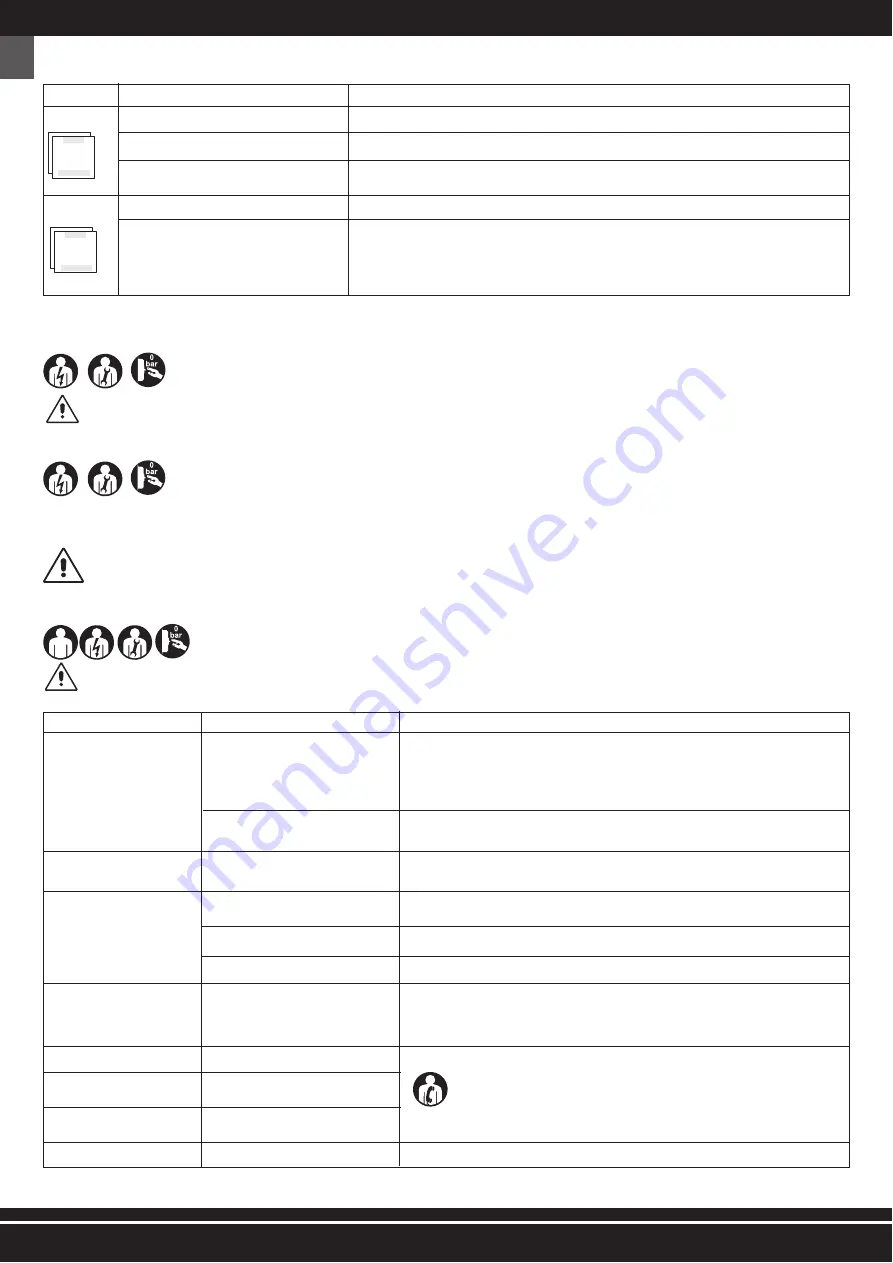
ROUTINE MAINTENANCE TABLE
FREQUENCY
POINT OF INTERVENTION
TYPE OF INTERVENTION
EVERY DAY
Safety devices
Make sure that they are integral, properly installed and working.
Power supply cable and plug
Visual check of the wear state.
Tank
At every work cycle end lean the machine on the ground and drain the condensate from the tank, opening the
condensate valve (FIG. 1 - Ref. 5).
EVERY WEEK
Wheels
Tire pressure control. If necessary, inflate with compressed air up to max. 2.5 bar
No.2 Air filters, front and rear side
Unscrew the screws (FIG. 6 - Ref. 1);
Remove the cover (FIG. 6 - Ref. 2);
Estract the filter (FIG. 6 - Ref. 3) and clean it with air;
Re-assemble the cover properly.
N.B.: REPLACE IN CASE OF CLEAR WEAR.
30- SUPPLEMENTARY MAINTENANCE
It includes all activities performed in order to maintain the proper use and operation conditions of the machine through different types of interventions (adjust-
ments, replacements, etc.) carried out exclusively by the technicians of the manufacturer at the established frequency or in case of failure or wear.
FOR ANY SUPPLEMENTARY MAINTENANCE INTERVENTION, COMPULSORY REQUEST THE TECHNICAL ASSISTANCE TO THE MANUFACTURER OF THE AUTHORIZED DEALER.
31- DEMOLITION
When the machine is demolished, compulsorily observe the provisions of the regulations in force.
Separate the parts making up the machine according to the different construction materials (plastic, copper, iron, etc.).
32- SPARE PARTS
ORIGINAL SPARE PARTS FOR POSSIBLE REPLACEMENTS ARE TO BE REQUESTED EXCLUSIVELY TO THE MANUFACTURER OR TO THE AUTHORIZED DEALER.
IT IS STRICTLY FORBIDDEN TO REPLACE ANY COMPONENTS OF THE MACHINE WITH NOT ORIGINAL SPARE PARTS.
33- TROUBLE - CAUSES - TROUBLESHOOTING
The following table gives a series of situations that can occur during the use of the machine.
THE AUTHORIZED OPERATORS MUST PERFORM EXCLUSIVELY THE OPERATIONS OF THEIR SPECIFIC COMPETENCE (SEE PAR. 2.2.1) AND WITH THE CONSENT OF THE COMPANY
SAFETY MANAGER (IF THE MACHINE IS USED IN A COMPANY).
TROUBLE
CAUSES
TROUBLESHOOTING
The machine does not switch on
or stops and does not restart.
Lack of power supply.
Tripping of the restorable thermal switch due
to current overload and/or short-circuit.
1)
Make sure that the “ON-OFF” switch is on pos. “ON (I)”;
2)
Check that the power supply cable plug is working and properly inserted in the suitable outlet;
3)
Check that possible extensions used and the power supply outlet are working;
4)
Check that the main switch of the mains is working and positioned on “ON (I)”.
Follow the procedure described in par. 26.
The machine starts many times
without using the tool.
Leaks from the air tube, the tool or the
pneumatic plant.
1)
Check that the pneumatic plant has not been damaged;
2)
Check the integrity and the connection of the air tube and of the tool.
Air does not come out from the
tool.
The tank is not under pressure.
Wrong adjustment of the output pressure.
The tool is damaged.
Switch on the machine and wait until the tank is loaded verifying the pressure on the proper pressure
gauge.
Check that the value indicated on the pressure gauge at output is greater than 0 (zero) bar.
Check the integrity and efficiency of the tool.
Pressure decrease in the air tank.
Leaks from the air tube, the tool or the
pneumatic plant.
1)
Check the integrity of the pneumatic plant.
2)
Check the integrity of the air tube and of the tool.
3)
Verify that the machine-air tube and air tube-tool connections are right.
4)
Make sure that the condensate drain valve is well closed.
Tripping of the safety valve.
Pressure switch faulty.
Air leak from the valve of the pres-
sure switch with stopped machine.
Check valve dirty or worn.
Apply to an authorized dealer.
The machine vibrates and/or emits
a lot of noise.
Mechanical break.
Frequent starts and low yield.
Air filters dirty.
Clean the filters (see par. 29).
GB


