Operating Instructions
Combined Wind Sensor ARCO SDI-12
(14582) ARCO SDI-12
Operating Instructions
When the tip of the vane points to the reference point, the
sensor can finally be attached with the two grub screws.
A functional test in three directions shifted each 90° is recom-
mended.
Observe all relevant safety instructions when mount-
ing a sensor on a mast.
2.7.2 Power supply and signal cables
As soon as the sensor is correctly mounted and connected to
the pre-assembled cable (accessory), the wires for the power
supply and the signal output can be connected.
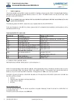
A 4-pin M12 cable connector is required for the electrical
connection of the sensor. The shielding of the cable must be
clamped at both ends to the protective conductor (PE).
To reduce the risk of inductive irradiation, the sensor
must be grounded correctly.
The external connection is made by means of a central plug
connector, which is protected in the device socket. Further de-
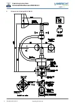
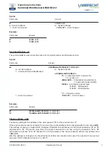
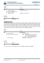
tails on the electrical connection of the sensor are shown in the
sections "Dimensioned drawing" and "Electrical connection".
The typical power supply of the sensors is 12 VDC with a
current consumption of 4 mA. The input voltage range can
be 9...15 VDC.
In case of possible icing or ice formation on the moving sensor
element, the function is limited for the duration of the icing.
The output signal of the sensor corresponds to the SDI-12
standard.
The sensor is ready for use 5 seconds after connection to the
power supply.
2.7.3 Safety regulations
Since the sensor is often mounted at great heights,
the relevant safety regulations must be followed dur-
ing installation. During the electrical installation work,
the relevant circuits must be disconnected from the
power supply.
The housing must only be opened by authorized
persons!
3 Maintenance
3.1
Regular maintenance and calibration
The sensors are designed to be very low-maintenance and for
a long service life. It is recommended that you carry out regu-
lar visual inspections for weather-related surface contamina-
tion and cleaning if necessary. A regular visual and functional
check of the wind sensors is recommended.
If reference measurements are required, it is essen-
tial to ensure that the measured values can only be
compared if the measurements are carried out under
the same conditions. This means that the reference
instrument must be used close to the sensor!
The sensor is a measuring instrument and is therefore subject
to the user's own recalibration cycle.
Manufacturer recommendation: 2 years.
We are pleased to offer you our qualified maintenance and
calibration services to ensure the long-term function and preci-
sion of the offered components.
3.2
Visual inspections and cleaning
The use of the sensor under the respective environmental
conditions requires appropriate actions. It is advisable to
clean the housing and the shelter at regular intervals. The
intervals depend on the ambient conditions and the degree
of contamination. A regular visual inspection and functional
test is recommended.
If problems arise during the tests which you cannot solve,
please contact Lambrecht meteo service:
Tel.:
+49-(0)551-4958-0
E-Mail: [email protected]
4 Transport
In the event that the sensor is to be shipped or transported by
you, it must be securely packed to avoid mechanical impact
or other damage.
5


