Operating Instructions
Combined Wind Sensor ARCO SDI-12
(14582) ARCO SDI-12
Operating Instructions
2.5
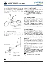
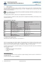
Mounting the cup rotor
The drill holes on the cup rotor are arranged in such a way
that it can only be mounted in a specific, unambiguous posi-
tion. All screws have to be used and the cup rotor or the wind
vane have to be fixed with them. This ensures the correct
direction of rotation. The required Allen key is included in the
scope of delivery.
1
Halbrundschraube mit Innensechskant
round head screw with hexagon socket
M3x8 DIN7380
2
Schalenstern / cup rotor
3
Schalensternglocke / cup rotor protective globe
4
Skt-Stiftschlüssel / hex head wrench
4
1
2
3
2.6
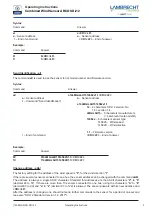
Mounting the wind vane
The wind vane can only be mounted in a specific position.
Use all 2 screws to attach the wind vane to the sensor head.
This is the only way to ensure a correct measurement of the
wind direction.
1
Schraube mit Innensechskant
screw with hexagon socket
M3x12 DIN7380
2
Windfahne / wind vane
3
Windfahnenglocke / wind vane protective globe
4
Skt-Stiftschlüssel / hex head wrench
4
1
2
3
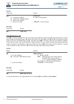
Please mount the wind vane on the upper part
and the cup rotor on the lower part of the sensor!
2.7
Installation procedure (brief description)
The sensor is installed in three steps:
(1) Attach the cable plug to the sensor and pull the cable
through the mast if necessary.
(2) Install the sensor on the mast, but before tightening the
screws you must align the sensor to the North.
(3) Connect the sensor connections for power supply and
signal output.
2.7.1 Mounting the sensor
The sensor is mounted on a mast piece (tube) with an outside
diameter of 50 mm and an inside diameter of at least 40 mm.
Before attaching the instrument with the two grub screws
M8 x 12, connect the cable, lead it through the pipe and align
the sensor to the north.
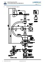
For this purpose, an appropriate marking is attached to the
instrument housing (see dimensioned drawing). Align the sen-
sor to the North before tightening the screws.
Please make sure that the sensor is firmly attached to the
mast!
Alignment of wind vane
To measure the wind direction, the sensor must be aligned
to the geographical North direction. In order to align the wind
sensor perfectly and firmly to the North, the device has an
integrated mounting aid. In the lower part of the sensor shaft
there is a grub screw with pin which can be turned inwards,
points to the North and is countersunk into the correspond-
ing slot of the mast (if present), so that the sensor is aligned
correctly and in a non-rotating manner. If necessary, the grub
screw can be turned in or out using an Allen key (see dimen-
sioned drawing).
Turn the mark on the wind vane exactly over the mark on the
sensor housing shaft. Fix this position of the wind vane, e.g.
with an adhesive strip. After alignment, remove the adhesive
strips again.
Now you can target the reference point via the axis of the
wind vane. The housing of the sensor must be turned on the
mounting tube so that the tip of the wind vane points to the
Northern reference point.
For the alignment, a point in the terrain is defined which is
as far North as possible in relation to the final position of the
wind direction sensor.
The position of the reference point can first be selected us-
ing a topographic map (1:25000). The exact position of the
reference point is determined with a compass, which can be
adjusted horizontally on a tripod.
Pay attention to compass misalignments!
4


