


25
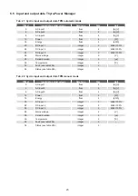
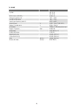
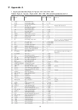
6.8 Input and output data Thyro-Measurement Unit
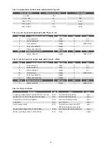
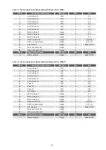
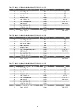
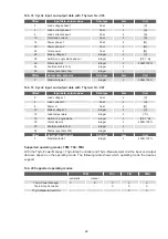
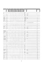
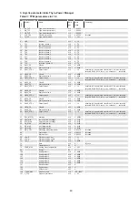
Tab. 25 Cyclic input and output data TMU mode
Offset
Input data, actual values
Data type
Size
Unit
0
AC input 1
float
4
[A],[V]
4
AC input 2
float
4
[A],[V]
8
AC input 3
float
4
[A],[V]
12
Power float
4
[W]
16
Energy
float
4
[kWh]
20
DC input 1
integer
2
4096=100%
22
DC input 2
integer
2
4096=100%
24
DC input 3
integer
2
4096=100%
26
Mains voltage
integer
2
[V]
28
Period duration
integer
2
[
μ
s]
30
Temperature integer
2
[°C]
32
Fault (see table 25b)
integer
2
-
34
Status (see table 25b)
integer
2
-
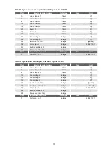
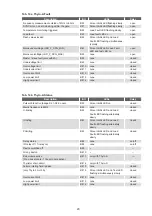
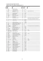
Tab. 25b Status TPM, TSC, TIO, TMU
Tab. 25b Fault TPM, TSC, TIO, TMU
Description
Bit
Fault LED, fault output*
Frequency measurement outside of 47Hz to 63Hz
Bit 0
on
SYNC error, no cero crossing within the gate
Bit 1
on
Temperature max. limit has been exceeded
Bit 2
on
Temperature min. limit has been exceeded
Bit 3
on
One or more parameters outside the limits
Bit 4
on
Mains voltage lower than lower voltage limit
Bit 5
on
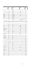
Description
Bit
Alarm LED, alarm output*
Mains frequency is 60Hz
Bit 2
off
Transformer 1 fallen below min. limit
Bit 3
on
Transformer 1 exceeded max. limit
Bit 4
on
Transformer 2 fallen below min. limit
Bit 5
on
Transformer 2 exceeded max. limit
Bit 6
on
Transformer 3 fallen below min. limit
Bit 7
on
Transformer 3 exceeded max. limit
Bit 8
on
Device switched off
Bit 9
--
Wrong device
Bit 10
--
Bus module active (0=no bus module / 1=bus module
active)
Bit 11
off
* Default setting can be parameterized.


