PPC-125 User Manual
30
5.1
Jumpers and Connectors
This chapter supplies more detailed information about the internal jumper settings
and an outline of the I/O ports available on the PPC-125
5.1.1 Setting Jumpers
The Panel PC can be configured to match the needs of each application by setting
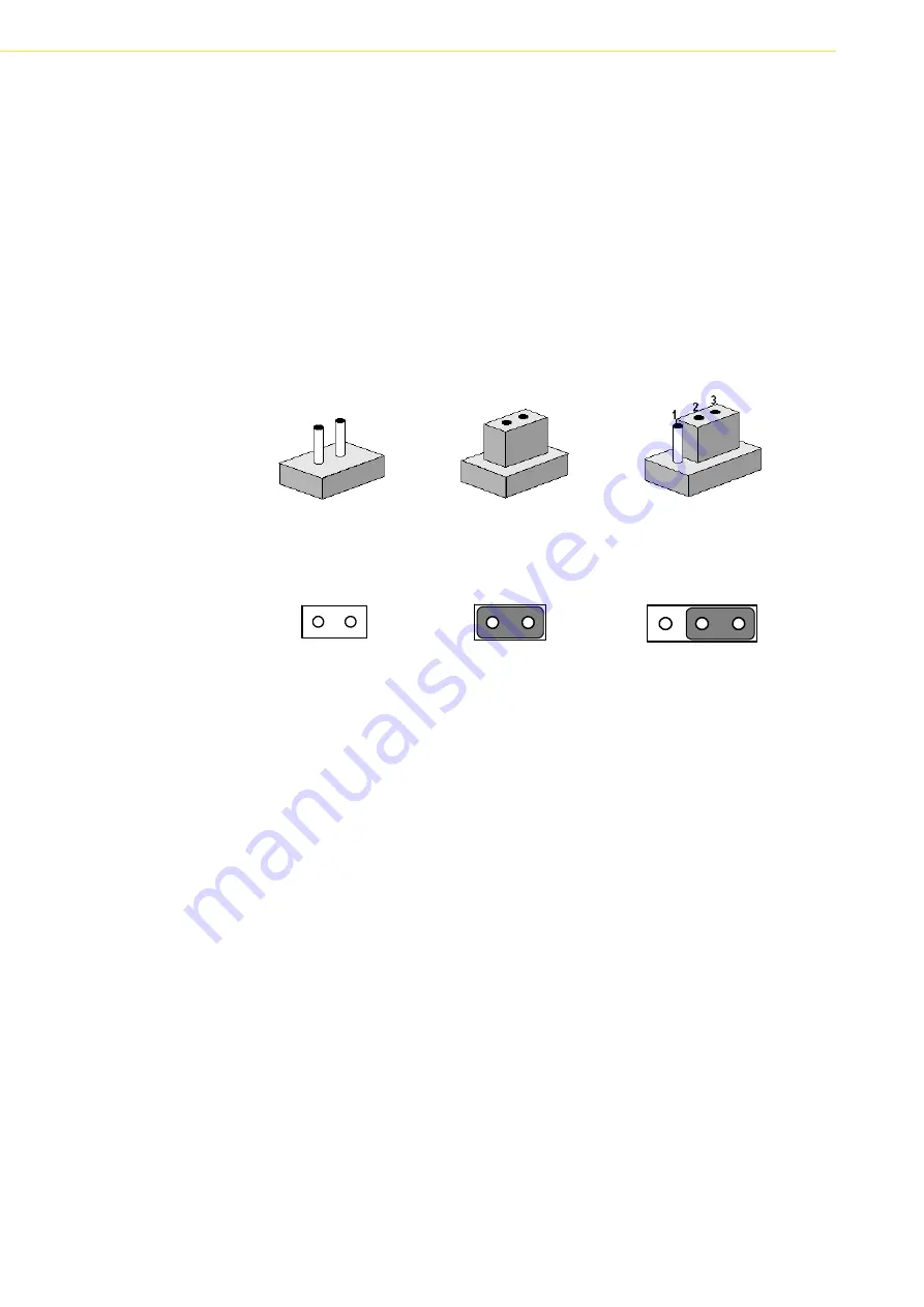
the jumpers. A jumper is the simplest kind of electrical switch. It consists of two metal
pins and a small metal clip (often protected by a plastic cover), which slides over the
pins to close the circuit and connect them. To ”close” a jumper, connect the pins with
the clip. To “open” a jumper, remove the clip. Sometimes a jumper has three pins,
labeled 1, 2, and 3. In this case, it is possible to connect either pins 1 and 2 or pins 2
and 3 to each other.
Open Closed Closed 2-3
The jumper settings are schematically depicted in this manual as follows:
Open Closed Closed 2-3
A pair of needle-nose pliers may be helpful when working with jumpers. If there are
any doubts about the best hardware configuration for a particular application, contact
the local distributor or sales representative before making any changes.
An arrow is printed on the motherboard to indicate the first pin of each jumper.
1
2
3
Summary of Contents for PPC-125
Page 1: ...User Manual PPC 125 Intel Core 2 Duo Processor Based Panel PC with 12 Color TFT LCD Display ...
Page 6: ...PPC 125 User Manual vi ...
Page 10: ...PPC 125 User Manual x ...
Page 14: ...PPC 125 User Manual 4 1 3 Dimensions Figure 1 1 Dimensions of PPC 125 ...
Page 20: ...PPC 125 User Manual 10 ...
Page 26: ...PPC 125 User Manual 16 ...
Page 38: ...PPC 125 User Manual 28 ...
Page 54: ...PPC 125 User Manual 44 ...
Page 58: ...PPC 125 User Manual 48 A 1 PCI Interface Card A 2 PCI E Interface Card ...
Page 59: ...49 PPC 125 User Manual Appendix A PCI Card and PCI E Size Limits ...


