PPC-125 User Manual
14
3.5
Serial COM Ports
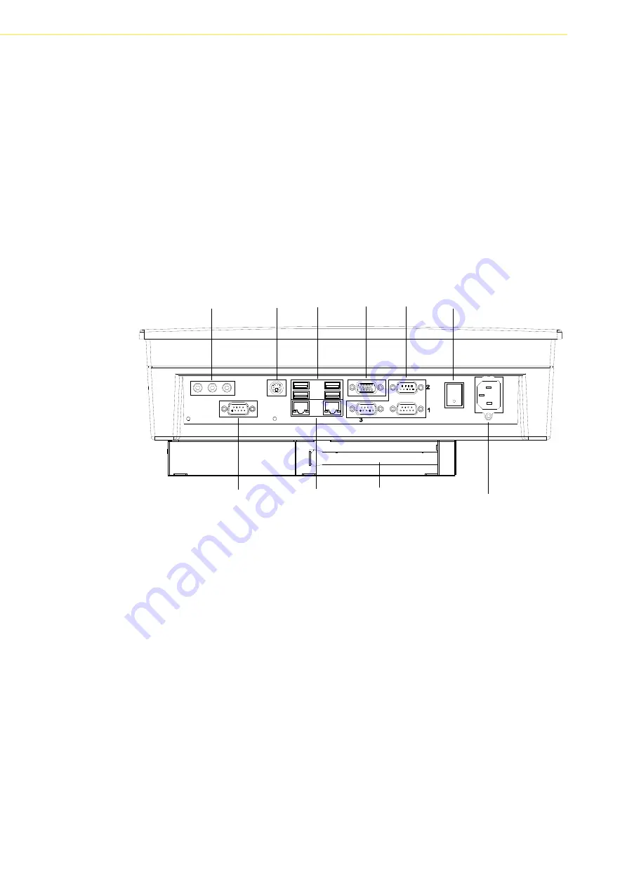
There are four serial COM ports on the bottom. It is simple to attach a serial device to
the panel PC, like an external modem or mouse. Follow these instructions:
1.
Be sure the panel PC and any other peripheral devices that are connected to
the panel PC are turned off.
2.
Attach the interface cable of the serial device to the panel PC's serial port. (See
Figure 3.3.) If necessary, attach the other end of the interface cable to the serial
device. Fasten any retaining screws.
3.
Turn on any other peripheral devices which are connected to the panel PC, and
then turn on the panel PC.
4.
Refer to the manual(s) which accompanied any serial device(s) for instructions
on configuring the operating environment to recognize the device(s).
5.
Run the BIOS setup program and configure the jumper settings to change the
mode of the COM ports.
Figure 3.3 I/O Ports
3.6
VGA Port
An external VGA-compatible device may be connected to the system through the 15-
pin external port located on the bottom of the system unit.
The panel PC simultaneously supports an external CRT monitor in addition to the
built-in LCD display.
1.
Be sure the panel PC is turned off.
2.
Connect the external monitor to the system. (See Figure 3.3.)
3.
Turn on the panel PC and the external monitor.
Audio Jacks KB/MS USB
VGA COM Power switch
AC Inlet
LAN
COM4
PCI Card slot
Summary of Contents for PPC-125
Page 1: ...User Manual PPC 125 Intel Core 2 Duo Processor Based Panel PC with 12 Color TFT LCD Display ...
Page 6: ...PPC 125 User Manual vi ...
Page 10: ...PPC 125 User Manual x ...
Page 14: ...PPC 125 User Manual 4 1 3 Dimensions Figure 1 1 Dimensions of PPC 125 ...
Page 20: ...PPC 125 User Manual 10 ...
Page 26: ...PPC 125 User Manual 16 ...
Page 38: ...PPC 125 User Manual 28 ...
Page 54: ...PPC 125 User Manual 44 ...
Page 58: ...PPC 125 User Manual 48 A 1 PCI Interface Card A 2 PCI E Interface Card ...
Page 59: ...49 PPC 125 User Manual Appendix A PCI Card and PCI E Size Limits ...


