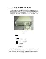
Momentary Switch
: Use this switch and by way of ATX (PS_ON)
function to turn on system power. Please use system shutdown to turn off
system power automatic or press momentary switch for a while to turn
off system power
USB connector:
If you have any USB interface device want to connect
with system, you could use this connector.
PS/2 connector:
If you want to connect PS/2 keyboard, you could use
this connector.
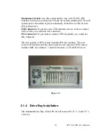
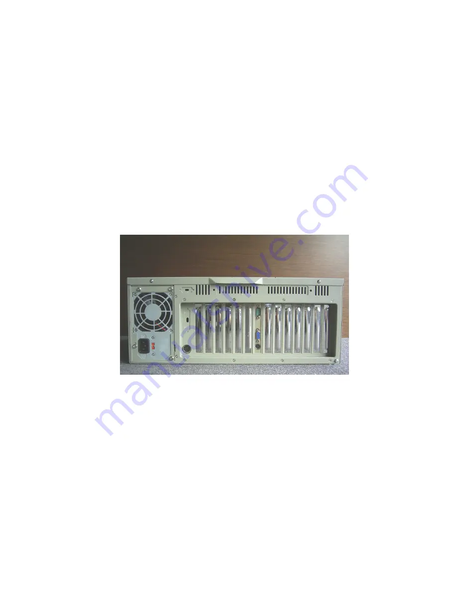
The rear section of B/P version includes B/P rear window. The rear
14-slot I/O brackets and the sheet metal kit for section of M/B version
includes M/B rear window, 7-slot I/O brackets, ATX M/B I/O cover.
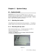
Figure 2-3
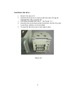
2.1.4 Drive Bay Installation
The Standard Drive Bay of the IPC-610-H can hold 5.25” x 3 and 3.5” x
1 devices
IPC-610-H User's Manual
10
Summary of Contents for IPC-610-H
Page 1: ...IPC 610 H 4U Rackmount Chassis User s Manual...
Page 6: ......
Page 7: ...General Information 1 CHAPTER...
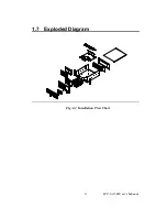
Page 12: ...1 7 Exploded Diagram Fig 1 2 Installation Flow Chart IPC 610 H User s Manual 6...
Page 13: ...System Setup 2 CHAPTER...
Page 22: ......
Page 23: ...Backplane A APPENDIX...

