
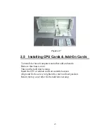


2.2 IPC-610-H Series Installation
The IPC-610-H can be of two basic models, IPC-610BP-00XH and
IPC-610MB-00XH.
2.2.1 IPC-610BP-00XH
IPC-610BP-00XH has no backplane, no power supply and has
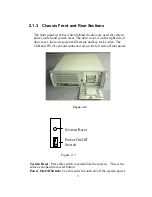
momentary switch on front panel. The momentary switch is suitable for
ATX power supply such as PS-250ATX-Z, PS-300ATX-Z.
For IPC-610BP-00XH, please plug 20-pin ATX power connector with
backplane first, then use a orange-white wire (1700030500) to connector
between CN# (PSON_GND_5VSB) of Backplane and “ATX feature
connector” (CN20) of SBC, finally connect POWER SW wire with the
“ATX soft power switch”(CN21) on SBC to finish the installation.
2.2.2 IPC-610MB-00XH
ACP-610MB-00X is for M/B using, it is with ATX M/B rear I/O.
ACP-610MB-00X is without M/B inside, has no power supply and has
momentary switch on front panel. The momentary switch is suitable for
ATX power supply such as PS-250ATX-Z, PS-300ATX-Z. For
ACP-610MB-00X, please plug 20-pin ATX power connector with your
ATX M/B, and then connect POWER SW wire with your ATX M/B to
finish the installation. Please refer your ATX M/B installation guide for
correct connection.
IPC-610-H User's Manual
12
Summary of Contents for IPC-610-H
Page 1: ...IPC 610 H 4U Rackmount Chassis User s Manual...
Page 6: ......
Page 7: ...General Information 1 CHAPTER...
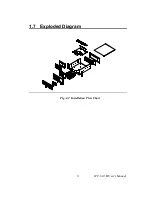
Page 12: ...1 7 Exploded Diagram Fig 1 2 Installation Flow Chart IPC 610 H User s Manual 6...
Page 13: ...System Setup 2 CHAPTER...
Page 22: ......
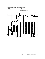
Page 23: ...Backplane A APPENDIX...


