

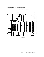
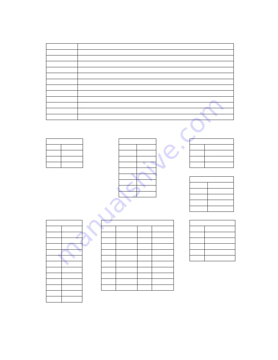
1. Connectors
Connector Description
ISA1, 4~10
16 Bit ISA Bus connectorr
PCI1~4
32 Bit PCI Bus connector
ISA 2, 3
PICMG connector
KB1
KB-In, from CPU card K/B connector
KB2~KB3
KB-Out, 5 pin extemal K/B connector
KB4
KB-Out, 6 pin PS/2 external K/ B connector
BIG1
Big 4 Pin Power connectorr
AT1
AT Power connector
ATX1
ATX Power connector
CN1
PS-ON Function, to CPU card for ATX power signal, 3 pin connector
CN2
8 pin Alarm Board Power connectorr
CN3
3 pin +5V and +12V Power connector
CN1
PIN Name
1 PS-ON
2 GND
3 5VSB
CN2
PIN Name
1 5VSB
2 GND
3 GND
4 -5V
5 +5V
6 +3.3V
7 -12V
8 +12V
CN3
PIN Name
1 +12V
2 GND
3 +5V
BIG1
PIN Name
1 +12V
2 GND
3 GND
4 +5V
AT1
PIN Name
1 NC
2 +5V
3 +12V
4 -12V
5 GND
6 GND
7 GND
8 GND
9 -5V
10 +5V
11 +5V
12 +5V
ATX1
PIN Name PIN Name
1 +3.3V
11 +3.3V
2 +3.3V
12 -12V
3 GND 13 GND
4 +5V 14 PS-ON
5 GND 15 GND
6 +5V 16 GND
7 GND 17 GND
8 NC 18 -5V
9 5VSB
19 +5V
10 +12V 20 +5V
KB1, 2, 3
PIN Name
1 KBCLK
2 KBDATA
3 NC
4 KBGND
5
KBVCC
Table 1.1 Connectors
19
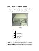
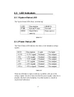
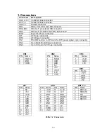
Summary of Contents for IPC-610-H
Page 1: ...IPC 610 H 4U Rackmount Chassis User s Manual...
Page 6: ......
Page 7: ...General Information 1 CHAPTER...
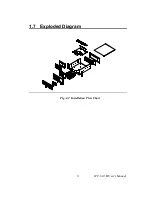
Page 12: ...1 7 Exploded Diagram Fig 1 2 Installation Flow Chart IPC 610 H User s Manual 6...
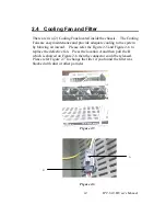
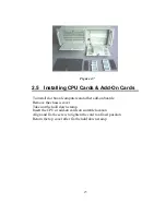
Page 13: ...System Setup 2 CHAPTER...
Page 22: ......
Page 23: ...Backplane A APPENDIX...


