background image

EKI-7720 Series User Manual

133

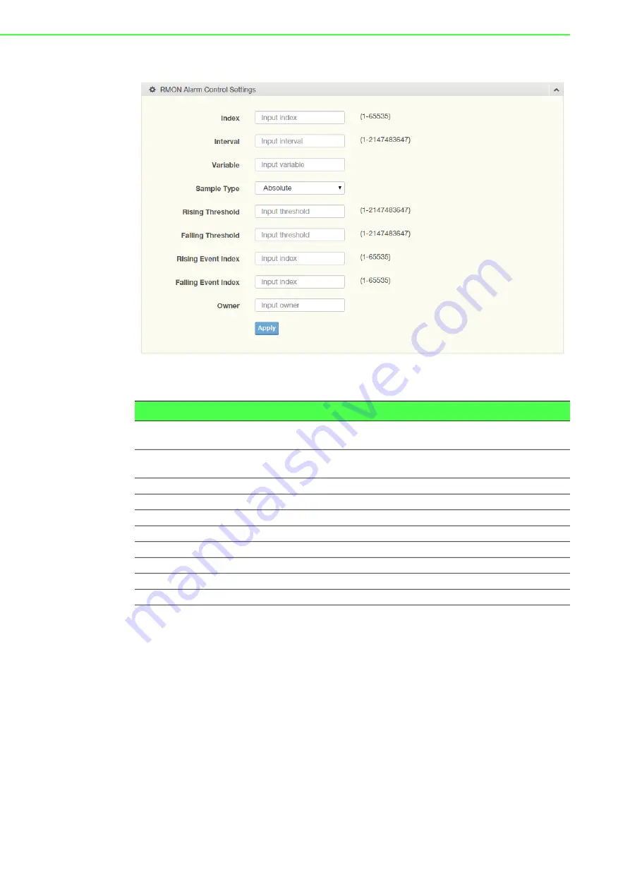
To access this page, click 

Management

 > 

RMON

 > 

RMON Alarm

.

Figure 4.205 Management > RMON > RMON Alarm

The following table describes the items in the previous figure.

The  ensuing  table  for 

Alarm  Information

  settings  are  informational  only:  Index,


Interval,  Variable,  Sample Type,  Rising Threshold,  Falling Threshold,  Rising  Event


Index, Falling Event Index, Owner and 

Delete

 (click to delete the desired index).

4.9.7.4

RMON Event

The RMON Event page is used to configure RMON event groups.

Item

Description

Index

Enter the index entry (1 to 65535) to define a specific Alarm Collection 

history entry.

Interval

Enter a value (1 to 2147483647) to define the interval value for the 

Alarm Collection history.

Variable

Enter the alarm variables to define the monitoring triggers.

Sample Type

Enter the variable sample type.

Rising Threshold

Enter the rising alarm threshold trigger.

Falling Threshold

Enter the falling alarm threshold trigger.

Rising Event Index

Enter the rising event index (1-65535) to define the alarm group.

Falling Event Index

Enter the falling event index (1-65535) to define the alarm group.

Owner

Enter the name of the owner of the RMON alarm group.

Apply

Click 

Apply

 to save the values and update the screen.

Summary of Contents for EKI-7712 Series

Page 1: ...User Manual EKI 7712 Series 8FE 4G 8GE 4G SFP port L2 Managed Switch ...

Page 2: ...oper installation Advantech assumes no liability under the terms of this warranty as a consequence of such events Because of Advantech s high quality control standards and rigorous testing most of our customers never need to use our repair service If an Advantech product is defec tive it will be repaired or replaced at no charge during the warranty period For out of warranty repairs you will be bi...

Page 3: ...and can radiate radio frequency energy and if not installed and used in accordance with the instruction manual may cause harmful interference to radio communications Opera tion of this equipment in a residential area is likely to cause harmful interference in which case the user will be required to correct the interference at his own expense Technical Support and Assistance 1 Visit the Advantech w...

Page 4: ...mmediately 1 x Industrial Ethernet Switch 2 x Wall mounting Bracket 1 x DIN Rail mounting Bracket and Screws Warning Warnings indicate conditions which if not observed can cause personal injury Caution Cautions are included to help you avoid damaging hardware or losing data e g There is a danger of a new battery exploding if it is incorrectly installed Do not attempt to recharge force open or heat...

Page 5: ...our any liquid into an opening This may cause fire or electrical shock 13 Never open the equipment For safety reasons the equipment should be opened only by qualified service personnel 14 If one of the following situations arises get the equipment checked by service personnel 15 The power cord or plug is damaged 16 Liquid has penetrated into the equipment 17 The equipment has been exposed to moist...

Page 6: ...te einen Brand bzw elektrischen Schlag aus lösen 13 Öffnen Sie niemals das Gerät Das Gerät darf aus Gründen der elektrischen Sicherheit nur von authorisiertem Servicepersonal geöffnet werden 14 Wenn folgende Situationen auftreten ist das Gerät vom Stromnetz zu trennen und von einer qualifizierten Servicestelle zu überprüfen 15 Netzkabel oder Netzstecker sind beschädigt 16 Flüssigkeit ist in das Ge...

Page 7: ...on period The following guidelines are also recommended Wear a grounded wrist or ankle strap and use gloves to prevent direct contact to the device before servicing the device Avoid nylon gloves or work clothes which tend to build up a charge Always disconnect the power from the device before servicing it Before plugging a cable into any port discharge the voltage stored on the cable by touching t...

Page 8: ...h to Console Port 20 2 7 Power Supply Installation 21 2 7 1 Overview 21 2 7 2 Considerations 22 2 7 3 Grounding the Device 22 2 7 4 Wiring a Relay Contact 23 2 7 5 Wiring the Power Inputs 24 2 8 Reset Button 25 Chapter 3 Configuration Utility 26 3 1 First Time Setup 27 3 1 1 Overview 27 3 1 2 Introduction 27 3 1 3 Administrative Interface Access 27 3 1 4 Using the Graphical Web Interface 28 3 1 5 ...

Page 9: ... 63 4 5 9 Jumbo Frame 68 4 5 10 Spanning Tree 68 4 5 11 X Ring Elite 74 4 5 12 X Ring Pro 75 4 5 13 Loopback Detection 78 4 5 14 ERPS 79 4 6 MAC Address Table 81 4 6 1 Static MAC 81 4 6 2 MAC Aging Time 81 4 6 3 Dynamic Forwarding Table 82 4 7 Security 83 4 7 1 Storm Control 83 4 7 2 Port Security 84 4 7 3 Protected Ports 85 4 7 4 DoS Prevention 85 4 7 5 Applications 88 4 7 6 802 1x 90 4 7 7 IP Se...

Page 10: ...9 4 10 5 DDM 141 4 10 6 LED Indication 142 4 11 Tools 143 4 11 1 IXM 143 4 11 2 Backup Manager 143 4 11 3 Upgrade Manager 144 4 11 4 Dual Image 145 4 11 5 Save Configuration 146 4 11 6 User Account 146 4 11 7 N Key 147 4 11 8 Reset System 147 4 11 9 Reboot Device 147 4 12 Modbus TCP Mapping 148 4 12 1 Modbus TCP Mapping Table 148 Chapter 5 Troubleshooting 160 5 1 Troubleshooting 161 ...

Page 11: ...stalling DC Wires in a Terminal Block 25 Figure 2 22 Securing a Terminal Block to a Receptor 25 Figure 4 1 Login Screen 33 Figure 4 2 Changing a Default Password 34 Figure 4 3 Monitoring Device Information 34 Figure 4 4 Monitoring Logging Message 35 Figure 4 5 Monitoring Logging Information 36 Figure 4 6 Monitoring Logging Message 36 Figure 4 7 Monitoring Port Monitoring Port Statistics 36 Figure ...

Page 12: ... 63 Figure 4 59 L2 Switching Multicast IGMP Snooping IGMP Settings 64 Figure 4 60 L2 Switching Multicast IGMP Snooping IGMP Snooping Information 64 Figure 4 61 L2 Switching Multicast IGMP Snooping IGMP Querier 64 Figure 4 62 L2 Switching Multicast IGMP Snooping IGMP Querier Status 65 Figure 4 63 L2 Switching Multicast IGMP Snooping IGMP Static Groups 65 Figure 4 64 L2 Switching Multicast IGMP Snoo...

Page 13: ...x Information 91 Figure 4 119 Security 802 1x 802 1x Port Configuration 91 Figure 4 120 Security IP Security Global Settings 92 Figure 4 121 Security IP Security Entry Settings 92 Figure 4 122 Security Security Login Global Settings Global Settings 93 Figure 4 123 Security Security Login Global Settings RADIUS Settings 93 Figure 4 124 Security Security Login Global Settings TACACS Settings 94 Figu...

Page 14: ...al Device Info 118 Figure 4 177 Management LLDP LLDP Local Device Info 118 Figure 4 178 Management LLDP LLDP Remote Device Info 118 Figure 4 179 Management LLDP LLDP Overloading 119 Figure 4 180 Management SNMP SNMP Settings 119 Figure 4 181 Management SNMP SNMP Community 120 Figure 4 182 Management SNMP SNMP Community 120 Figure 4 183 Management SNMP SNMPv3 EngineID 120 Figure 4 184 Management SN...

Page 15: ...g Server 140 Figure 4 214 Diagnostics DDM Diagnostic Alarm Settings 141 Figure 4 215 Diagnostics DDM DMI INFO 141 Figure 4 216 Diagnostics LED Indication 142 Figure 4 217 Diagnostics LED Indication 142 Figure 4 218 Tools IXM 143 Figure 4 219 Tools Backup Manager 144 Figure 4 220 Tools Upgrade Manager 145 Figure 4 221 Tools Dual Image 145 Figure 4 222 Tools User Account 146 Figure 4 223 Tools User ...

Page 16: ...Chapter 1 1Product Overview ...

Page 17: ...larm PoE only for EKI 7712G 4FP and EKI 7712G 4FPI Port LED Speed Link Activity Environment Operating Tem perature Standard Temperature 10 C 60 C 14 F 140 F Wide Temperature 40 C 75 C 40 F 167 F Storage Tempera ture 40 C 85 C 40 F 185 F Ambient Relative Humidity 10 95 non condensing Switch Properties MAC Address 8K entry Switching Capac ity EKI 7712G 4F EKI 7712G 4FI 24 Gbps EKI 7712E 4F EKI 7712E...

Page 18: ...evel 3 EN 61000 4 4 EFT Level 3 EN 61000 4 5 Surge Level 3 EN 61000 4 6 CS Level 3 EN 61000 4 8 Magnetic Field Level 3 Only for EKI 7712P series EN 61000 4 2 ESD Level 4 EN 61000 4 3 RS Level 4 EN 61000 4 4 EFT Level 4 EN 61000 4 5 Surge Level 4 EN 61000 4 6 CS Level 4 EN 61000 4 8 Magnetic Field Level 4 Shock IEC 60068 2 27 Freefall IEC 60068 2 32 Vibration IEC 60068 2 6 Traffic Control NEMA TS2 ...

Page 19: ... ports x 8 3 LNK ACT LED Link activity LED 4 Speed LED Orange 100M Green 1G 5 System LED panel See System LED Panel on page 6 for further details 6 Reset button Button allows for system soft reset or factory default reset 7 Console serial port Console cable port to COM port DB9 male on computer to RS232 managed switch RJ45 female EKI 7712E Console LNK ACT 9 10 11 12 9 10 11 12 Reset SYS R M PWR1 P...

Page 20: ...ty LED 4 Speed LED Orange 100M Green 1G 5 System LED panel See System LED Panel only for PoE model on page 7 for further details 6 Reset button Button allows for system soft reset or factory default reset 7 Console serial port Console cable port to COM port DB9 male on computer to RS232 managed switch RJ45 female EKI 7712G Console LNK ACT 9 10 11 12 9 10 11 12 Reset SYS R M PWR1 PWR2 Alarm 2 4 6 8...

Page 21: ...tem crash oper ation initiating 2 R M Solid green Active when determining ring master 3 PWR1 Solid green Powered up Off Powered down or not installed 4 PWR2 Solid green Powered up Off Power down or not installed 5 Alarm Solid red Defined major policies are detected Blinking Red Defined minor policies are detected Off Powered off or system is operating normally SYS R M PWR1 PWR2 Alarm 1 2 3 4 5 ...

Page 22: ...wn system crash oper ation initiating 2 R M Solid green Active when determining ring master 3 PWR1 Solid green Powered up Off Powered down or not installed 4 PWR2 Solid green Powered up Off Power down or not installed 5 Alarm Solid red Defined major policies are detected Blinking Red Defined minor policies are detected Off Powered off or system is operating normally 6 PoE depending the PoE ports S...

Page 23: ...2 Rear View Figure 1 5 Rear View No Item Description 1 Wall mounting holes Screw holes x6 used in the installation of a wall mounting plate 2 DIN Rail mounting plate Mounting plate used for the installation to a standard DIN rail 2 1 1 ...

Page 24: ... 7712E 4FP and EKI 7712E 4FPI Figure 1 7 Top View No Item Description 1 Ground terminal Screw terminal used to ground chassis 2 Terminal block Connect cabling for power and alarm wiring No Item Description 1 Ground terminal Screw terminal used to ground chassis 2 Terminal block Connect cabling for power and alarm wiring V2 V2 PWR2 PWR1 P Fail V1 V1 DC12 48V 1A 24V 1 2 V2 V2 PWR2 PWR1 P Fail V1 V1 ...

Page 25: ...Chapter 2 2Switch Installation ...

Page 26: ...t proper airflow the switch can overheat To prevent performance degredation and damage to the switch make sure there is clerance at the top and bottom and around the exhaust vents 2 1 1 Connecting Hardware In this instruction it will explain how to find a proper location for your Modbus Gate ways and how to connect to the network hock up the power cable and connect to the EKI 7712 Series 2 2 Verif...

Page 27: ... DIN rail clip hooks over the top of the DIN rail as shown in the following illustration Make sure the DIN rail is inserted behind the spring mechanism 2 Once the DIN rail is seated correctly in the DIN rail clip press the front of the switch to rotate the switch down and into the release tab on the DIN rail clip If seated correctly the bottom of the DIN rail should be fully inserted in the releas...

Page 28: ...n of a completed DIN installation proce dure Figure 2 2 Correctly Installed DIN Rail Kit 3 Grasp the bottom of the switch and slightly rotate it upwards If there is resis tance the switch is correctly installed Otherwise re attempt the installation pro cess from the beginning ...

Page 29: ...tion resistance than the DIN rail vertical mount Before the device can be mounted on a wall you will need to remove the DIN rail plate 1 Rotate the device to the rear side and locate the DIN mounting plate 2 Remove the screws securing the DIN mounting plate to the rear panel of the switch 3 Remove the DIN mounting plate Store the DIN mounting plate and provided screws for later use 4 Align the wal...

Page 30: ...les over the four marked locations on the wall keeping in mind that the holes must accommodate wall sinks in addition to the screws 9 Insert the wall sinks into the walls 10 Insert the screws into the wall sinks Leave a 2 mm gap between the wall and the screw head to allow for wall mount plate insertion Figure 2 5 Securing Wall Mounting Screws 11 Align the wall mount plate over the screws on the w...

Page 31: ...ement The concept behind the LC port and cable is quite straight forward Suppose that you are connecting devices I and II contrary to electrical signals optical signals do not require a circuit in order to transmit data Consequently one of the optical lines is used to transmit data from device I to device II and the other optical line is used transmit data from device II to device I for full duple...

Page 32: ...ule is seated correctly before sliding the module into the slot A click sounds when it is locked in place Figure 2 8 Installing an SFP Transceiver 6 Remove the protective plug from the SFP transceiver Note Do not remove the dust plug from the SFP slot if you are not installing the transceiver at this time The dust plug protects hardware from dust contamination Note If you are attaching fiber optic...

Page 33: ...les To disconnect an LC connector use the following guidelines 1 Press down and hold the locking clips on the upper side of the optic cable 2 Pull the optic cable out to release it from the transceiver Figure 2 10 Removing a Fiber Optic Cable to a Transceiver 3 Hold the handle on the transceiver and pull the transceiver out of the slot Figure 2 11 Removing an SFP Transceiver Note Replace the dust ...

Page 34: ...RJ45 Ethernet ports are metallic and con nected to the GND terminal For best performance use shielded cabling Shielded cabling may be used to provide further protection Figure 2 12 Ethernet Plug Connector Pin Position Maximum cable length 100 meters 328 ft for 10 100 1000BaseT Straight thru Cable Wiring Cross over Cable Wiring Pin 1 Pin 1 Pin 1 Pin 3 Pin 2 Pin 2 Pin 2 Pin 6 Pin 3 Pin 3 Pin 3 Pin 1...

Page 35: ...s RJ45 RJ45 port a wired connection for management can be established Figure 2 13 Serial Console Cable Figure 2 14 DB 9 Pin Position Figure 2 15 Pin Assignment DB9 Connector RJ45 Connector NC 1 Orange White NC 2 Orange 2 3 Green White NC 4 Blue 5 5 Blue White 3 6 Green NC 7 Brown White NC 8 Brown To terminal or PC To console port 5 9 1 6 3 6 8 1 7 2 5 4 TXD RJ45 Male RXD NC NC NC NC GND GND 2 3 7 ...

Page 36: ...ime as a result of power loss EKI 7712G 4F EKI 7712G 4FI EKI 7712E 4F EKI 7712E 4FI support 12 to 48 VDC and EKI 7712G 4FP EKI 7712G 4FPI support 48 VDC Dual power inputs are sup ported and allow you to connect a backup power source Figure 2 16 Power Wiring for EKI 7712 Series Warning Power down and disconnect the power cord before servicing or wiring the switch Caution Do not disconnect modules o...

Page 37: ...to the various devices for more effective manage ment and servicing 2 7 3 Grounding the Device Note Routing communications and power wiring through the same conduit may cause signal interference To avoid interference and signal degra dation route power and communications wires through separate con duits Caution Do not disconnect modules or cabling unless the power is first switched off The device ...

Page 38: ...of the relay output The terminal block on the EKI 7712 Series is wired and then installed onto the terminal receptor located on the EKI 7712 Series Figure 2 18 Terminal Receptor Relay Contact The terminal receptor includes a total of six pins two for PWR1 two for PWR2 and two for a fault circuit Caution Do not block air ventilation holes Note Before applying power to the grounded switch it is advi...

Page 39: ...tor 2 Remove the terminal block from the switch Figure 2 20 Removing a Terminal Block 3 Insert a small flat bladed screwdriver in the V1 V1 wire clamp screws and loosen the screws 4 Insert the negative positive DC wires into the V V terminals of PW1 If setting up power redundancy connect PW2 in the same manner Caution Do not disconnect modules or cabling unless the power is first switched off The ...

Page 40: ...inal block to secure it to the terminal block recep tor If there is no gap between the terminal block and the terminal receptor the ter minal block is seated correctly Figure 2 22 Securing a Terminal Block to a Receptor 2 8 Reset Button Reset configuration to factory default Press and hold Reset button for 5 seconds System reboot Press and hold Reset button for 2 seconds 1 A 2 4 V 1 A 2 4 V Loosen...

Page 41: ...Chapter 3 3Configuration Utility ...

Page 42: ...f explanation of how RSTP works is given in the Spanning Tree section The switch is capable of communicating with other SNMP capable devices on the network to exchange management information This statistical derived information from the network is saved in the Management Information Base MIB of the switch The MIB is divided into several different information storage groups These groups will be ela...

Page 43: ...dress Here to reach the System Settings menu The settings in this menu control the switch s general net work configuration DHCP Enabled Disabled The switch can automatically obtain an IP address from a server using the Dynamic Host Configuration Protocol DHCP This can speed up initial set up as the network administrator does not have to find an open IP address IP Address and subnet mask configurat...

Page 44: ...h is selected Choose to enable auto negotiation or use fixed settings 100Mbps Fiber ports are Fixed speed only Speed Duplex Flow Control The managed switch accepts three local area net work Ethernet Standards The first standard 10BASE T runs 10Mbps with twisted pair Ethernet cable between network interfaces The second local area network standard is 100BASE T which runs at 100Mbps over the same twi...

Page 45: ...il explicitly committed Sections and parameter names are case sensitive e g Network is not the same as network 3 2 2 Accessing the CLI To access the CLI interface establish Ethernet or serial connectivity to the switch To connect by Ethernet open a command prompt window and type telnet switchip where switchip is the IP address of the switch At the login prompt type cli for the username and admin f...

Page 46: ...ollows IP address 192 168 1 1 Subnet mask 255 255 255 0 Default gateway 192 168 1 254 User name admin Password admin 3 3 2 System Login Once the switch is installed and connected power on the switch The following infor mation guides you through the logging in process 1 Launch your web browser on the PC 2 In the browser s address bar type the switch s default IP address 192 168 1 1 The login screen...

Page 47: ...Chapter 4 4Managing Switch ...

Page 48: ...en 4 2 Recommended Practices One of the easiest things to do to help increase the security posture of the network infrastructure is to implement a policy and standard for secure management This practice is an easy way to maintain a healthy and secure network After you have performed the basic configurations on your switches the following is a recommendation which is considered best practice policy...

Page 49: ...ddress Firmware version and more pertaining to the system The information is for review only To modify the device information see the respective item within the user interface To access this page click Monitoring Device Information Figure 4 3 Monitoring Device Information The following table describes the items in the previous figure Item Description System Name Click Switch to enter the system na...

Page 50: ...re build date of the switch Build Version Displays the current firmware build version of the switch System Object ID Displays the base object ID of the switch System Up Time Displays the time since the last switch reboot Item Description Item Description Target Click the drop down menu to select a target to store the log mes sages Buffered Store log messages in RAM All log messages are cleared aft...

Page 51: ...put The monitoring func tionality includes listing of port statistics as well as port utilization 4 3 3 1 Port Statistics To access this page click Monitoring Port Monitoring Port Statistics Figure 4 7 Monitoring Port Monitoring Port Statistics The following table describes the items in the previous figure View Click View to display all Logging Information and Logging Message information Refresh C...

Page 52: ...mation for Ether Like MIB Counters settings Figure 4 9 Monitoring Port Monitoring Ether Like MIB Counters The following table provides information for RMON MIB Counters settings Figure 4 10 Monitoring Port Monitoring Ether Like MIB Counters 4 3 3 2 Port Utilization To access this page click Monitoring Port Monitoring Port Utilization Figure 4 11 Monitoring Port Monitoring Port Utilization ...

Page 53: ...ch trunk It displays membership status link state and membership type for each port To access this page click Monitoring Link Aggregation Figure 4 13 Monitoring Link Aggregation 4 3 5 LLDP Statistics The LLDP Statistics page displays the LLDP statistics Item Description Refresh period Click the drop down menu to select and designate a period second intervals to refresh the information TX and RX li...

Page 54: ...wing figure displays the LLDP Port Statistics settings Figure 4 15 Monitoring LLDP Port Statistics 4 3 6 IGMP Statistics The IGMP Statistics function displays statistical package information for IP multi casting Item Description Clear Click Clear to reset LLDP Statistics of all the interfaces Refresh Click Refresh to update the data on the screen with the present state of the data in the switch ...

Page 55: ... Other RX Leave RX Report RX General Query RX Special Group Query RX Special Group Source Query RX Leave TX Report TX General Query TX Special Group Query TX and Special Group Source Query TX 4 3 7 MLD Statistics The MLD Statistics function displays statistical package information for MLD mes sage Item Description Clear Click Clear to refresh IGMP Statistics of all the interfaces Refresh Click Ref...

Page 56: ...s are informational only Total RX Valid RX Invalid RX Other RX Leave RX Report RX General Query RX Special Group Query RX Special Group Source Query RX Leave TX Report TX General Query TX Special Group Query TX and Special Group Source Query TX Item Description Clear Click Clear to refresh MLD Statistics of all the interfaces Refresh Click Refresh to update the data on the screen with the present ...

Page 57: ...n Item Description Mode Click the radio button to select the IP Address Setting mode Static or DHCP IP Address Enter a value to specify the IP address of the interface The default is 192 168 1 1 Subnet Mask Enter a value to specify the IP subnet mask for the interface The default is 255 255 255 0 Gateway Enter a value to specify the default gateway for the interface The default is 192 168 1 254 DN...

Page 58: ...v6 Information 4 4 3 DHCP Client Option 82 The DHCP Client Option 82 configurable Circuit ID and Remote ID feature enhances validation security by allowing you to select naming choices suboptions You can select a switch configured hostname or specify an ASCII test string for the remote ID You can also configure an ASCII text string to override the circuit ID Item Description Auto Configuration Sel...

Page 59: ...e the DHCP Client Option 82 mode Circuit ID Format Click the drop down menu to set the ID format String Hex User Defi nition Circuit ID String Enter the string ID of the corresponding class Circuit ID Hex Enter the hex string of the corresponding class Circuit ID User Define Enter the user definition of the corresponding class Remote ID Format Click the drop down menu to set the Remote ID format S...

Page 60: ...gh the TFTP server To access this page click System DHCP Auto Provision Figure 4 24 System DHCP Auto Provision The following table describes the items in the previous figure The following figure displays the DHCP Auto Provision Information settings Figure 4 25 System DHCP Auto Provision Information 4 4 5 Management VLAN By default the VLAN is the management VLAN providing communication with the sw...

Page 61: ...e are informational only Management VLAN 4 4 6 System Time To access this page click System System Time Figure 4 27 System System Time The following table describes the items in the previous figure Item Description Management VLAN Click the drop down menu to select a defined VLAN Apply Click Apply to save the values and update the screen Item Description Enable SNTP Click the radio button to enabl...

Page 62: ...o 65535 default 123 Manual Time Click the drop down menus to set local date and time of the system Time Zone Click the drop down menu to select a system time zone Daylight Saving Time Click the drop down menu to enable or disable the daylight saving time settings Daylight Saving Time Offset Enter the offsetting variable in seconds to adjust for daylight saving time Recurring From Click the drop do...

Page 63: ...nter the port number in the field HTTPS By default the HTTPS port setting is set to port 443 To assign the web interface to a different port enter the port number in the field TELNET By default the TELNET port setting is set to port 23 To assign the web interface to a different port enter the port number in the field SSH By default the SSH port setting is set to port 22 To assign the web interface...

Page 64: ...rop down menu to select the port speed Auto Auto 10M Auto 100M Auto 1000M Auto 10 100M 10M 100M or 1000M Duplex Click the drop down menu to select the duplex setting Auto Half or Full Flow Control Click the radio button to enable or disable the flow control function Downshift Click the radio button to enable or disable the downshift function for speed Fiber Port Click the drop down menu to select ...

Page 65: ...layed values do not represent the actual setting values To access this page click L2 Switching Port Mirror Figure 4 33 L2 Switching Port Mirror The following table describes the items in the previous figure Item Description Session ID Click the drop down menu to select a port mirroring session from the list The number of sessions allowed is platform specific Monitor session state Click the drop do...

Page 66: ...ancy in case one of the links should fail 4 5 3 1 Load Balance The Load Balancing page allows you to select between a MAC Address or IP MAC Address algorithm for the even distribution of IP traffic across two or more links To access this page click L2 Switching Link Aggregation Load Balance Figure 4 36 L2 Switching Link Aggregation Load Balance Sniffer RX Ports Enter the variable to define the RX ...

Page 67: ...itching Link Aggregation LAG Management Figure 4 38 L2 Switching Link Aggregation LAG Management The following table describes the items in the previous figure Item Description Load Balance Algo rithm Select the radio button to select the Load Balance Setting MAC Address IP MAC Address or Source Port Apply Click Apply to save the values and update the screen Item Description LAG Click the drop dow...

Page 68: ...itching Link Aggregation LAG Port Settings Figure 4 40 L2 Switching Link Aggregation LAG Port Settings The following table describes the items in the previous figure Item Description LAG Select Click the drop down menu to select a predefined LAG trunk definition LAG 1 8 Enabled Click the radio button to enable or disable the LAG Port Speed Click the drop down menu to select the port speed Auto Aut...

Page 69: ... for LACP Information settings are informational only System Pri ority 4 5 3 5 LACP Port Settings Link Aggregation Control Protocol LACP provides a method to control the bundling of several physical ports together to form a single logical channel By configuring the LACP function the switch can negotiate an automatic bundling of links by sending LACP packets to the peer device also implementing LAC...

Page 70: ...1 VLAN Management The management of VLANs is available through the VLAN Settings page Through this page you can add or delete VLAN listings and add a prefix name to an added entry Item Description Port Select Select a port for the LACP Port Settings The listed available settings are FE1 FE8 GE1 GE2 However the available settings are dependent on the connected LACP device and may not be listed as d...

Page 71: ...le the ingress filtering To access this page click L2 Switching 802 1Q VLAN PVID Settings Figure 4 47 L2 Switching 802 1Q VLAN PVID Settings The following table describes the items in the previous figure Item Description VLAN Action Click the radio button to add or delete the VLAN entry shown in the previous field VLAN ID VLAN List Enter the name of the VLAN entry to setup VLAN Name VLAN Prefix En...

Page 72: ...k the radio button to specify which frames to forward Tag Only discards any untagged or priority tagged frames Untag Only discards any tagged frames All accepts all untagged and tagged frames Whichever you select VLAN tagged frames are forwarded in accor dance with the IEEE 802 1Q VLAN standard The default is All Ingress Filtering Click the radio button to specify how you want the port to handle t...

Page 73: ... previous figure Item Description Port Displays the assigned port to the entry Interface VLAN Mode Displays the Hybrid mode to the listed VLAN port Membership Displays the assigned membership status of the port entry options include Forbidden Excluded Tagged or Untagged Apply Click Apply to save the values and update the screen ...

Page 74: ...ble to have more than the 4094 separate VLANs allowed by 802 1Q There are three ways in which a machine can be connected to a network carrying double tagged 802 1ad traffic via a untagged port where both inner and outer VLANs are handled by the switch or switches so the attached machine sees ordinary Ethernet frames via a single tagged tunnel port where the outer VLAN only is handled by the switch...

Page 75: ...AN Ether type Enter the outer VLAN handled by the switch giving the attached machine a single tagged 802 1Q VLAN frame Apply Click Apply to save the values and update the screen Item Description Port Select Enter the switch port part of VLAN configuration to configure the selection as a tunnel port Outer PVID Enter the Port VLAN ID PVID to assigned the native VLAN ID All untagged traffic coming in...

Page 76: ...conds Enter a number between 6 and 600 An instance of this timer exists for each GARP participant for each port Leave Time Enter a value to specify the time to wait after receiving an unregister request for a VLAN or multicast group before deleting the associated entry in centiseconds This allows time for another station to assert registration for the same attribute in order to maintain uninterrup...

Page 77: ...e The ensuing table for GMRP Information settings are informational only GMRP The ensuing table for Multicast Groups settings are informational only VLAN ID MAC Address Type and Member Ports 4 5 7 802 3az EEE The 802 3az Energy Efficient Ethernet EEE innovative green feature reduces energy consumption through intelligent functionality Traffic detection Energy Efficient Ethernet EEE compliance Inac...

Page 78: ...rt To access this page click L2 Switching Multicast Multicast Filtering Figure 4 58 L2 Switching Multicast Multicast Filtering The following table describes the items in the previous figure The ensuing table for Properties Information settings are informational only Unknown Multicast Action 4 5 8 2 IGMP Snooping IGMP Snooping is defined as the process of listening to Internet Group Management Prot...

Page 79: ...Querier allows snooping to function by creating the tables for snooping Gen eral queries must be unconditionally forwarded by all switches involved in IGMP snooping To access this page click L2 Switching Multicast IGMP Snooping IGMP Querier Figure 4 61 L2 Switching Multicast IGMP Snooping IGMP Querier The following table describes the items in the previous figure Item Description IGMP Snooping Sta...

Page 80: ...oups The following figure displays the Multicast Groups settings Figure 4 64 L2 Switching Multicast IGMP Snooping Multicast Groups Router Ports To access this page click L2 Switching Multicast IGMP Snooping Router Ports The following figure displays the Router Ports settings Figure 4 65 L2 Switching Multicast IGMP Snooping Router Ports Querier State Select Disable or Enable to configure the VLAN I...

Page 81: ...owing table describes the items in the previous figure The following figure displays the MLD Snooping Information settings Figure 4 67 L2 Switching Multicast MLD Snooping MLD Snooping Information The following figure displays the MLD Snooping Table settings Figure 4 68 L2 Switching Multicast MLD Snooping MLD Snooping Table Item Description MLD Snooping State Select Enable or Disable to setup the M...

Page 82: ... MLD Static Group Figure 4 70 L2 Switching Multicast MLD Snooping MLD Static Group The following table describes the items in the previous figure The ensuing table for MLD Static Groups Status settings are informational only VLAN ID Group IP Address Member Ports and Modify Item Description VLAN ID Enter the VLAN ID to configure Querier State Select Enable or Disable status on the selected VLAN Ena...

Page 83: ...uration of Ethernet frame size To access this page click L2 Switching Jumbo Frame Figure 4 73 L2 Switching Jumbo Frame The following table describes the items in the previous figure The ensuing table for Jumbo Frame Config settings are informational only Jumbo Frame Bytes 4 5 10 Spanning Tree The Spanning Tree Protocol STP is a network protocol to ensure loop free topology for any bridged Ethernet...

Page 84: ...io button to enable or disable the STP status BPDU Forward Select flooding or filtering to designate the type of BPDU packet BPDU Guard Click the radio button to enable or disable the BPDU guard When enabled BPDU Guard can disable edge ports that receive BPDU packets This prevents a new device from entering the existing STP topology Thus devices that were originally not a part of STP are not allow...

Page 85: ...to this setting Admin Enable Select Enabled or Disabled to setup the admin profile for the STP port Path Cost 0 Auto Set the port s cost contribution For a root port the root path cost for the bridge 0 means Auto Edge Port Click the drop down menu to set the edge port configuration No Force to false state as link to a bridge Yes Force to true state as link to a host P2P MAC Click the drop down men...

Page 86: ... to select the port list to apply this setting To access this page click L2 Switching Spanning Tree STP Port Advanced Settings Figure 4 78 L2 Switching Spanning Tree STP Port Advanced Settings The following table describes the items in the previous figure Item Description Priority Click the drop down menu to select the STP bridge priority Forward Delay Enter the variable 4 to 30 to set the forward...

Page 87: ...revious figure The ensuing table for MST Configuration Identification Information settings are informational only Configuration Name and Revision Level 4 5 10 6 MST ID Settings The MST Instance ID Settings page allows you to edit the MSTI ID and VID List set tings Priority Click the drop down menu to designate a priority Apply Click Apply to save the values and update the screen Item Description I...

Page 88: ...rity Settings Figure 4 82 L2 Switching Spanning Tree MSTI Priority Settings The following table describes the items in the previous figure The ensuing table for MSTI Priority Information settings are informational only MSTI ID Priority and Action 4 5 10 8 MSTI Bridge Info To access this page click L2 Switching Spanning Tree MSTI Bridge Info Item Description MSTI ID Enter the MST instance ID 0 15 V...

Page 89: ...vanced settings 4 5 10 10STP Statistics To access this page click L2 Switching Spanning Tree STP Statistics The following figure displays the STP Statistics settings Figure 4 85 L2 Switching Spanning Tree STP Statistics 4 5 11 X Ring Elite The X Ring Elite function provides an improvement over Spanning Tree and Rapid Spanning Tree and a rapid auto recovery in the event that the network suffers a c...

Page 90: ...g ID Role Port 1 Port 2 and Delete click to delete the desired Ring ID 4 5 12 X Ring Pro The X Ring Pro function provides an improvement over Spanning Tree and Rapid Spanning Tree and a rapid auto recovery in the event that the network suffers a cor rupt or broken link and prevents network loops 4 5 12 1 X Ring Pro Settings The X Ring Pro Settings page allows you to configure the status enabled or...

Page 91: ... items in the previous figure Figure 4 90 L2 Switching X Ring Pro X Ring Pro Groups Chain Settings The following table describes the items in the previous figure Item Description State Select Enabled or Disabled to setup the X Ring Pro mode Apply Click Apply to save the values and update the screen Item Description Ring ID Enter a number to specifies a ranging from 1 to 255 to identify a given X R...

Page 92: ...on Couple Ring ID Enter a number to specifies a ranging from 1 to 255 to identify a given X Ring group Port Enter the port to assign to define the couple setting Master Ring ID Click the drop down menu to designate the master ring Add Click Add to save the values and update the screen Item Description Pair Ring ID Enter a number to specifies a ranging from 1 to 255 to identify a pair ring ID Port ...

Page 93: ...al Settings The following table describes the items in the previous figure To access this page click L2 Switching Loopback Detection Loopback Detec tion Global Information The following figure displays the Loopback Detection Global Information settings Figure 4 95 L2 Switching Loopback Detection Loopback Detection Global Information 4 5 13 2 Port Settings The Port Settings page allows you to selec...

Page 94: ...ss this page click L2 Switching ERPS ERPS Settings Figure 4 97 L2 Switching ERPS ERPS Settings The following table describes the items in the previous figure The ensuing table for Information settings are informational only ERPS State Item Description Port Select Enter the port to define the local loopback detection setting Enabled Select Enabled or Disabled to setup the Loopback Detection func ti...

Page 95: ...the value to set the ring ID Role Click the drop down menu to select the role Options include RPL Owner RPL Neighbor or Other East Link Enter the port to define the east link RPL Check the check box to enable RPL West Link Enter the port to define the west link RPL Check the check box to enable RPL MEL Enter the value to set minimum equipment list R APS Channel VLAN Click the drop down menu to sel...

Page 96: ...his page click MAC Address Table Static MAC Status The following figure displays the Static MAC Status settings Figure 4 100 MAC Address Table Static MAC Status 4 6 2 MAC Aging Time The MAC Aging Time page allows you to set the MAC address of the aging time to study To access this page click MAC Address Table MAC Aging Time Figure 4 101 MAC Address Table MAC Aging Time Item Description MAC Address...

Page 97: ...Address Information The following figure displays the MAC Address Information settings Figure 4 103 MAC Address Table MAC Address Information Item Description Aging Time Enter the variable 10 to 630 to define the time required for aging Apply Click Apply to save the values and update the screen Item Description Port Click the drop down menu to select the port number to show or clear dynamic MAC en...

Page 98: ... Storm Control Storm Control Global Infor mation The following figure displays the Storm Control Global Information settings Figure 4 105 Security Storm Control Storm Control Global Information 4 7 1 2 Port Settings The Port Settings page allows you to configure the port and the type of storm control association along with the value of the storm rate for the selected port Item Description Unit Sel...

Page 99: ...llows you to configure port isolation behavior Item Description Port Enter the port number to designate the local port for the Storm Control function Port State Select Disabled or Enabled to define the port state Action Click the drop down menu to select the type of action to designate for the selected port during a Storm Control incident The options are Drop and Shutdown Type Enable Click the rad...

Page 100: ...uing table for Protected Ports Status settings are informational only Pro tected Ports and Unprotected Ports 4 7 4 DoS Prevention The DoS Prevention page allows you to setup enabled or disabled the denial of ser vice Item Description Port Select Enter a single or multiple port numbers to configure Enabled Select Enabled or Disabled to define the selected Port FDB Learn Limit 0 64 Enter the variabl...

Page 101: ...ettings The following table describes the items in the previous figure Item Description DMAC SMAC Click Enabled or Disabled to define DMAC SMAC for the DoS Global settings LAND Click Enabled or Disabled to define LAND for the DoS Global set tings UDP Blat Click Enabled or Disabled to define UDP Blat for the DoS Global set tings TCP Blat Click Enabled or Disabled to define TCP Blat for the DoS Glob...

Page 102: ...led to set a maximum ping size for the IPv6 protocol Ping Max Size Set ting Enter the variable in bytes 0 to 65535 to set the maximum ping size Smurf Attack Click Enabled or Disabled to set the Smurf Attack function TCP Min Hdr Size Click Enabled or Disabled to set the minimum header size Enter the variable in bytes 0 to 31 to set the minimum header size TCP SYN SPORT 1024 Click Enabled or Disable...

Page 103: ...pplications TELNET The following table describes the items in the previous figure The ensuing table for Telnet Information settings are informational only Telnet Ser vice and Current Telnet Sessions Count 4 7 5 2 SSH Secure Shell SSH is a protocol providing secure encrypted management connec tion to a remote device Item Description Port Select the port to configure for the DoS prevention function ...

Page 104: ...s figure The ensuing table for HTTP Information settings are informational only HTTP Ser vice and Session Timeout 4 7 5 4 HTTPS The HTTPS page allows you to combine all kinds of AAA lists on the HTTPS line Attempts to access the switch s Web UI from HTTPS are first authenticated Item Description SSH Service Click Enabled or Disabled to set up Ethernet encapsulation remote access through the Secure...

Page 105: ... disabled for the selected IP server address port accounting port and associated password including a reauthentication period To access this page click Security 802 1x 802 1x Global Settings Figure 4 117 Security 802 1x 802 1x Global Settings The following table describes the items in the previous figure Item Description HTTPS Service Click Enabled or Disabled to set up Ethernet encapsulation over...

Page 106: ...u a means to configure the IP Security settings Server Port Enter the port number 1 to 65535 assigned to the listed Server IP Accounting Port Enter the port number 1 to 65535 assigned to the listed server IP configured to provide authorization and authentication for network access Security Key Enter the variable to define the network security key used in authenti cation Reauth Period Enter the var...

Page 107: ...click Security IP Security Entry Settings Figure 4 121 Security IP Security Entry Settings The following table describes the items in the previous figure The ensuing table for IP Security Entry Information settings are informational only IP Address IP Mask Services and Action Item Description Status Click Enabled or Disabled to define the global setting for the IP secu rity function Apply Click Ap...

Page 108: ... to set up security login global setting sta tus Apply Click Apply to save the values and update the screen Item Description Server IP Enter the IP address of the local server providing authentication func tion Server Port Enter the port number 1 to 65535 assigned to the listed Server IP Security Key Enter the variable to define the network security key used in authenti cation Auth Type Click the ...

Page 109: ...s Control Settings This function specifies the login authentication type for the system To access this page click Security Security Login Security Login Access Control Settings Figure 4 126 Security Security Login Access Control Settings Security Login Type Settings Item Description Server IP Enter the IP address of the local server providing authentication func tion Server Port Enter the port num...

Page 110: ...nformation 4 7 9 Access Control List The Access Control List is the basic traffic filter for ingress and egress packets Allow user to filter criteria for diverse protocols and deny access to specific source or desti nation IP MAC addresses 4 7 9 1 MAC ACL Entry Settings Item Description Login Type Click to select the login type Options include None Used RADIUS Only TACACS Only RADIUS TACACS or RAD...

Page 111: ...nter the MAC address to set source MAC address Source MAC Mask Enter a value to specify the subnet mask for the source MAC address Ether Type Enter a value to specify the DNS server for the interface VLAN ID Type in the value designating the VLAN ID Portlist Select the port to configure for the MAC ACL function Action Click the drop down menu to select the MAC ACL action Options include Permit Dro...

Page 112: ... items in the previous figure Item Description Entry ID Type in the value designating the entry ID Destination IP Address Enter the IP address to set destination IP address Destination IP Mask Enter a value to specify the subnet mask for the destination IP address Source IP Address Enter the IP address to set source IP address Source IP Mask Enter a value to specify the subnet mask for the source ...

Page 113: ...ard Global Settings Figure 4 133 Security IP Source Guard Global Settings The following table describes the items in the previous figure Portlist Select the port to configure for the IP ACL function Action Click the drop down menu to select the IP ACL action Options include Permit Drop or Assign Queue Assign Queue Click the drop down menu to select the queue The function is only available when Act...

Page 114: ...The following table describes the items in the previous figure To access this page click Security IP Source Guard Entry Information The following figure displays the Entry Information settings Figure 4 136 Security IP Source Guard Entry Information Item Description Source MAC Address Enter the MAC address to set source MAC address Source IP Address Enter the IP address to set source IP address Por...

Page 115: ...g Binding Port Settings The following table describes the items in the previous figure Item Description DHCP Snooping State Click Enabled or Disabled to set DHCP snooping state Apply Click Apply to save the values and update the screen Item Description DHCP Snooping Port Select Select the port to configure for the DHCP Snooping port Enabled Click Enabled or Disabled to enable DHCP Snooping port Ap...

Page 116: ...s the L2 Relay State settings Figure 4 142 Security DHCP Snooping L2 Relay Settings The following table describes the items in the previous figure To access this page click Security DHCP Snooping L2 Relay Port Settings The following figure displays the L2 Relay Port settings Figure 4 143 Security DHCP Snooping L2 Relay Port Settings The following table describes the items in the previous figure To...

Page 117: ... Snooping L2 Relay Information The following figure displays the L2 Relay Information settings Figure 4 146 Security DHCP Snooping L2 Relay Information The following table describes the items in the previous figure Item Description L2 Relay VLAN List Enter the port number to add the corresponding port to the relay Enabled Click Enable or Disable to set the function state Apply Click Apply to save ...

Page 118: ...o access this page click Security Entry Information The following figure displays the Entry Information settings Figure 4 148 Security Entry Information The following table describes the items in the previous figure Item Description Source MAC Address Enter the MAC address to set source MAC address Source IP Address Enter the IP address to set source IP address Add Click Add to add an ARP spoofing...

Page 119: ...etwork makes performance predictable and bandwidth utilization much more effective The QoS implementation is based on the prioritization values in Layer 2 frames 4 8 1 1 QoS Properties The QoS Properties allows you to set the QoS mode To access this page click QoS General QoS Properties Figure 4 149 QoS General QoS Properties The following table describes the items in the previous figure The ensui...

Page 120: ... on the user priority specification to indicate the importance weight of the queue relative to the other CoS queues WRR scheduling prevents low priority queues from being completely ignored during periods of high priority traffic The WRR scheduler sends some packets from each queue in turn Item Description Port Enter the port number to associate with the QoS setting CoS Value Click the drop down m...

Page 121: ...eneral QoS Information 4 8 1 4 CoS Mapping The CoS Mapping allows you to apply CoS mapping Item Description Queue Queue entry for egress port Strict Select Strict to assign the scheduling designation to the selected queue WRR Select WRR to assign the scheduling designation to the selected queue Weight Enter a queue priority weight relative to the defined entries WRR only of WRR Bandwidth Displays ...

Page 122: ...pping Information settings Figure 4 155 QoS General CoS Mapping To access this page click QoS General CoS Mapping Item Description CoS to Queue Mapping Class of Service Displays the CoS for the queue entry Queue Click the drop down menu to select the queue priority for selected CoS Queue to CoS Mapping Queue Displays the queue entry for CoS mapping Class of Service Click the drop down menu to sele...

Page 123: ...Mapping Figure 4 157 QoS General DSCP Mapping The following table describes the items in the previous figure The ensuing table for DSCP Mapping Information settings are informational only DSCP and Mapping to Queue The ensuing table for Queue Mapping Information settings are informational only Queue and Mapping to DSCP Item Description DSCP to Queue Mapping DSCP Enter the DSCP entry to define the p...

Page 124: ...vice QoS allows to give preferential treatment to certain types of traffic at the expense of others Without QoS the switch offers best effort service to each packet regardless of the packet contents or size sending the packets without any assurance of reliability delay bounds or throughput QoS mode supports two modes 802 1p and DSCP Item Description IP Precedence to Queue Mapping IP Precedence Dis...

Page 125: ...gs page allows you to define a trust state enabled or disabled to a listed port To access this page click QoS QoS Basic Mode Port Settings Figure 4 161 QoS QoS Basic Mode Port Settings The following table describes the items in the previous figure The ensuing table for QoS Port Status settings are informational only Port and Trust State Item Description Trust Mode Click the drop down menu to selec...

Page 126: ...owing figure displays the Ingress Bandwidth Control Recover Time set tings Figure 4 163 QoS Rate Limit Ingress Bandwidth Control To access this page click QoS Rate Limit Ingress Bandwidth Control The following figure displays the Ingress Bandwidth Control Status settings Figure 4 164 QoS Rate Limit Ingress Bandwidth Control 4 8 3 2 Egress Bandwidth Control The Egress Bandwidth Control page allows ...

Page 127: ...s settings Figure 4 166 QoS Rate Limit Egress Bandwidth Control 4 8 3 3 Egress Queue The Egress Queue page allows you to set the egress bandwidth parameters To access this page click QoS Rate Limit Egress Queue Figure 4 167 QoS Rate Limit Egress Queue Item Description Port Enter the port number to set the Egress Bandwidth Control State Select Disabled or Enabled to set the Egress Bandwidth Control...

Page 128: ...e drop down menu to select the port to define the Egress queue Queue Click the drop down menu to set the queue order for the Egress set ting State Click Disabled or Enabled to set the Egress queue state CIR Kbps Enter the value in Kbps 16 to 1000000 to set the CIR rate for the Egress queue Apply Click Apply to save the values and update the screen Item Description Status Click Disabled or Enabled ...

Page 129: ...lobal Settings 4 8 4 2 Utilization To access this page click QoS Bandwidth Guarantee Utilization Figure 4 170 QoS Bandwidth Guarantee Utilization The following table describes the items in the previous figure Item Description Refresh period Click the drop down menu to select refresh time Apply Click Apply to save the values and update the screen ...

Page 130: ...tems in the previous figure To access this page click Management LLDP LLDP System Settings The following figure displays the LLDP Global Config settings Figure 4 172 Management LLDP LLDP System Settings Item Description Enabled Click Enabled or Disabled to set the Global Settings state LLDP PDU Disable Action Click to select the LLDP PDU handling action when LLDP is globally disabled Options inclu...

Page 131: ... items in the previous figure The following figure displays the Optional TLVs Selection settings Figure 4 174 Management LLDP LLDP Port Settings Optional TLVs Selection The following table describes the items in the previous figure Item Description Port Select Enter the port number associated with the LLDP setting State Click the drop down menu to select the LLDP port state Apply Click Apply to sa...

Page 132: ... System Name To include system name TLV in LLDP frames Port Description To include port description TLV in LLDP frames System Description To include system description TLV in LLDP frames System Capability To include system capability TLV in LLDP frames 802 3 MAC PHY To indicate the current duplex and bit rate set tings of the device 802 3 Link Aggregation To indicate the link can be aggregated 802...

Page 133: ...LDP Remote Device Info page allows you to view information about remote devices LLDP information must be available on the switch To access this page click Management LLDP LLDP Remote Device Info Figure 4 178 Management LLDP LLDP Remote Device Info The following table describes the items in the previous figure 4 9 1 5 LLDP Overloading To access this page click Management LLDP LLDP Overloading Item ...

Page 134: ...this page click Management SNMP SNMP Settings Figure 4 180 Management SNMP SNMP Settings The following table describes the items in the previous figure The ensuing table for SNMP Information settings are informational only SNMP 4 9 2 2 SNMP Community The SNMP Community page provides configuration options for the community SNMP v1 and SNMP v2c use the group name Community Name certification It s ro...

Page 135: ...v3 EngineID Figure 4 183 Management SNMP SNMPv3 EngineID The following table describes the items in the previous figure 4 9 2 4 SNMPv3 Settings The SNMPv3 Settings page allows you to create SNMP groups The users have the same level of security and access control permissions as defined by the group set tings Item Description Community Name Enter a community name up to 20 characters Access Right Cli...

Page 136: ...rofile Access Right Click read only or read write to define the access right for the profile Encrypted Click the option to set the encrypted option for the user setting Auth Protocol Click the drop down menu to select the authentication level MD5 or SHA The field requires a user password MD5 specify HMAC MD5 96 authentication level SHA specify HMAC SHA authentication protocol Password Enter the ch...

Page 137: ...er over Ethernet can be used for the following areas Surveillance devices I O sensors for security requirements Wireless access points 4 9 3 1 PoE System Settings The PoE System Settings page allows you to configure the overload disconnect and the maximum available wattage Item Description IP Address Enter the IP address to designate the SNMP trap host Community Name User Name Click the drop down ...

Page 138: ...us its power limita tions legacy mode status and power limit settings To access this page click Management Power Over Ethernet PoE Port Set tings Figure 4 187 Management Power Over Ethernet PoE Port Settings The following table describes the items in the previous figure Item Description Maximum Power Available Select the value in Watts to set the maximum available power OverLoad Discon nect Mode C...

Page 139: ...ttings TCP Modbus Settings The following table describes the items in the previous figure To access this page click Management TCP Modbus Settings TCP Modbus Settings The following figure displays the TCP Modbus Status settings Figure 4 189 Management TCP Modbus Settings TCP Modbus Settings Power Limit From Classification Select Enabled or Disabled to designate the power limit classifica tion Lega...

Page 140: ... for Status Information settings are informational only DHCP Server Service 4 9 5 2 Global Settings The Global Settings page allows you to configure the global settings for the DHCP function To access this page click Management DHCP Server Global Settings Figure 4 191 Management DHCP Server Global Settings Item Description DHCP Server Select Enable or Disable to designate the DHCP server function ...

Page 141: ...Time Type in the value designating the lease time 60 864000 in seconds for each setting lease Low IP Address Type in the value designating the lowest range in the IP address pool High IP Address Type in the value designating the highest range in the IP address pool Subnet Mask Type in the value designating the subnet mask for the IP address pool Gateway Type in the value designating the gateway fo...

Page 142: ...ntry for the Option 82 setting Circuit ID Format Click the drop down menu to select the format of the circuit ID string or hex Circuit ID Content Enter the circuit ID string on the switch on which the request was received Remote ID Format Click the drop down menu to select the format of the remote ID string or hex Remote ID Content Enter the remote ID string of the host Low IP Address Type in the ...

Page 143: ... Address Subnet Mask and Modify Click Detail to dis play the detail information of desired entry id or Delete to delete the desired entry id 4 9 5 6 Lease Entry To access this page click Management DHCP Server Lease Entry Item Description Entry ID Type in the value designating the entry ID Client MAC Address Enter the MAC address for DHCP server IP Address Enter a value to specify the IP address o...

Page 144: ...k Management SMTP Client Global Settings Figure 4 198 Management SMTP Client Global Settings The following table describes the items in the previous figure The ensuing table for SMTP Information settings are informational only Active Pro file Id 4 9 6 2 Profile Settings The Profile Settings page allows you to select the server IP the server port and sender mail for the listed profile To access thi...

Page 145: ...essage page allows you to setup the log message for use with the SMTP client Item Description Profile ID Click the drop down menu to select the identification type for the pro file 1 or 2 Server IP Enter the IP address to designate the server host Server Port Enter the port number to designate the port associated with the server IP address Sender Mail Enter the email address of the sender client A...

Page 146: ... view information regarding packet sizes and information for physical layer errors The information displayed is according to the RMON standard To access this page click Management RMON RMON Statistics Figure 4 203 Management RMON RMON Statistics Item Description Title Assign the title of the email The maximum length is 20 characters alphanumeric symbols dot _ underline dash line and space Content ...

Page 147: ... and Delete click to delete the desired index 4 9 7 3 RMON Alarm The RMON Alarm page allows you to configure RMON statistics group and alarm groups Item Description Index Enter an entry selection 1 to 65535 to display its statistical informa tion Port Enter the respective port number for the selected entry Owner Enter the name of the owner of the RMON group Apply Click Apply to save the values and...

Page 148: ...iption Index Enter the index entry 1 to 65535 to define a specific Alarm Collection history entry Interval Enter a value 1 to 2147483647 to define the interval value for the Alarm Collection history Variable Enter the alarm variables to define the monitoring triggers Sample Type Enter the variable sample type Rising Threshold Enter the rising alarm threshold trigger Falling Threshold Enter the fal...

Page 149: ...Delete click to delete the desired index Item Description Index Enter the index entry 1 to 65535 to define a specific RMON event Description Enter a value 1 to 2147483647 to define the interval value for the Alarm Collection history Type Click the drop down menu to define the event type None Log SNMP Trap Log and Trap Community Enter the community string to be passed for the specified event Owner ...

Page 150: ...n Value Server 1 Server 2 Server 3 Server 4 Server 5 Server 6 Server 7 Server 8 Server 9 and Server 10 Item Description NTP Server Click the radio button to enable or disable the NTP server function Manual Time Click the radio button to enable or disable the manual time function Server Address 1 Server Address 10 Enter the address of the NTP server This is a text string of up to 64 characters cont...

Page 151: ... in the previous figure The ensuing table for Test Result settings are informational only Port Channel A Cable Length A Channel B Cable Length B Channel C Cable Length C Channel D and Cable Length D 4 10 2 Ping Test The Ping Test page allows you to configure the test log page To access this page click Diagnostics Ping Test Figure 4 209 Diagnostics Ping Test Item Description Port Click the drop dow...

Page 152: ... ping packets in seconds The default value is 1 The value ranges from 1 to 5 The interval entered is not retained across a power cycle Size in bytes Enter the size of ping packet The default value is 56 The value ranges from 8 to 5120 The size entered is not retained across a power cycle Ping Results Display the reply format of ping PING 172 17 8 254 172 17 8 254 56 data bytes 172 17 8 254 ping st...

Page 153: ...abels concatenated with dots Each label must be between 1 and 63 characters long and the entire hostname has a maximum of 64 characters Count Enter the number of echo requests you want to send The default value is 4 The value ranges from 1 to 5 The count you enter is not retained across a power cycle Interval in sec Enter the interval between ping packets in seconds The default value is 1 The valu...

Page 154: ...g Figure 4 212 Diagnostics System Log Local Logging Ping Results Display the reply format of ping PING 2222 777 2222 777 56 data bytes 2222 777 ping statistics 4 packets transmitted 0 packets received 100 packet loss Or PING 2222 717 2222 717 56 data bytes 64 bytes from 2222 717 icmp6_seq 0 ttl 128 time 10 0 ms 64 bytes from 2222 717 icmp6_seq 1 ttl 128 time 0 0 ms 64 bytes from 2222 717 icmp6_seq...

Page 155: ...evious figure Item Description Target Enter the local logging target Severity Click the drop down menu to select the severity level for local log messages The level options are emerg Indicates system is unusable It is the highest level of severity alert Indicates action must be taken immediately crit Indicates critical conditions error Indicates error conditions warning Indicates warning condition...

Page 156: ...p down menu to select the severity level for local log messages The default is emerg The level options are emerg Indicates system is unusable It is the highest level of severity alert Indicates action must be taken immediately crit Indicates critical conditions error Indicates error conditions warning Indicates warning conditions notice Indicates normal but significant conditions info Indicates in...

Page 157: ...is page click Diagnostics LED Indication The following figure displays the LED Information settings Figure 4 217 Diagnostics LED Indication Item Description High Alarm Click Enabled or Disabled to set the alarm state High Warning Click Enabled or Disabled to set the alarm state Low Alarm Click Enabled or Disabled to set the alarm state Low Warning Click Enabled or Disabled to set the alarm state A...

Page 158: ...up Manager page allows you to configure a remote TFTP sever or host file system in order to backup the firmware image or configuration file Item Description Search Field Enter criteria to search the IXM information Displays the reference to the device number Device Name Displays the device name Device Model Displays the device model type Category Displays the device s category type IP Address Disp...

Page 159: ...ile system in order to upload firmware upgrade images or configuration files Item Description Backup Method Click the drop down menu to select the backup method TFTP or HTTP Server IP Enter the IP address of the backup server Backup Type Click a type to define the backup method image running configura tion startup configuration custom configuration flash log or buffered log Image Click the format ...

Page 160: ...n the previous figure Item Description Upgrade Method Click the drop down menu to select the upgrade method TFTP or HTTP Server IP Enter the IP address of the upgrade server File Name Enter the file name of the new firmware version Upgrade Type Click a type to define the upgrade method image startup configura tion running configuration or custom configuration Image Click the format for the image t...

Page 161: ...ameters To access this page click Tools User Account Figure 4 222 Tools User Account The following table describes the items in the previous figure 4 11 6 2 Wrong Password To access this page click Tools User Account The following figure displays the Wrong Password settings Figure 4 223 Tools User Account Item Description User Name Enter the name of the new user entry Password Type Click the drop ...

Page 162: ... that have been made will be lost even if you have issued a save Click Select Excepted Configuration to keep the configuration you selected when resetting Reset settings take effect after a system reboot 4 11 9 Reboot Device To access this page click Tools Reboot Device Item Description State Click to enable or disable the wrong password detection function Retry Time Enter a variable to designate ...

Page 163: ...001 30002 Unit ID 0xFF Product Code 1 word 16 bits HEX 0x0002 30003 Product Code Vendor Name Advantech 16 words 32 chars ASCII 0x0010 30017 Vendor Name Advant ech Word 0 Hi byte A Word 0 Lo byte d Word 1 Hi byte v Word 1 Lo byte a Word 2 Hi byte n Word 2 Lo byte t Word 3 Hi byte e Word 3 Lo byte c Word 4 Hi byte h Word 4 Lo byte 0 Product Name EKI xxxx 16 words 32 chars ASCII 0x0020 30033 Product ...

Page 164: ...x1008 34105 Port 10 Status 1 word 16 bits HEX 0x1009 34106 Port 11 Status 1 word 16 bits HEX 0x100A 34107 Port 12 Status 1 word 16 bits HEX 0x100B 34108 Port 13 Status 1 word 16 bits HEX 0x100C 34109 Port 14 Status 1 word 16 bits HEX 0x100D 34110 Port 15 Status 1 word 16 bits HEX 0x100E 34111 Port 16 Status 1 word 16 bits HEX 0x100F 34112 Port 17 Status 1 word 16 bits HEX 0x1010 34113 Port 18 Stat...

Page 165: ...34369 Port 18 Speed 1 word 16 bits HEX 0x1111 34370 Port 19 Speed 1 word 16 bits HEX 0x1112 34371 Port 20 Speed 1 word 16 bits HEX 0x1113 34372 Port 21 Speed 1 word 16 bits HEX 0x1114 34373 Port 22 Speed 1 word 16 bits HEX 0x1115 34374 Port 23 Speed 1 word 16 bits HEX 0x1116 34375 Port 24 Speed 1 word 16 bits HEX 0x1117 34376 Port 25 Speed 1 word 16 bits HEX 0x1118 34377 Port 26 Speed 1 word 16 bi...

Page 166: ...rd 16 bits HEX 0x1211 34626 Port 19 Flow Control 1 word 16 bits HEX 0x1212 34627 Port 20 Flow Control 1 word 16 bits HEX 0x1213 34628 Port 21 Flow Control 1 word 16 bits HEX 0x1214 34629 Port 22 Flow Control 1 word 16 bits HEX 0x1215 34630 Port 23 Flow Control 1 word 16 bits HEX 0x1216 34631 Port 24 Flow Control 1 word 16 bits HEX 0x1217 34632 Port 25 Flow Control 1 word 16 bits HEX 0x1218 34633 P...

Page 167: ... words 40 chars ASCII 0x148C 35261 Port 9 Description 20 words 40 chars ASCII 0x14A0 35281 Port 10 Description 20 words 40 chars ASCII 0x14B4 35301 Port 11 Description 20 words 40 chars ASCII 0x14C8 35321 Port 12 Description 20 words 40 chars ASCII 0x14DC 35341 Port 13 Description 20 words 40 chars ASCII 0x14F0 35361 Port 14 Description 20 words 40 chars ASCII 0x1504 35381 Port 15 Description 20 w...

Page 168: ...k Up Counter 1 word 16 bits HEX 0x1702 35891 Port 4 Link Up Counter 1 word 16 bits HEX 0x1703 35892 Port 5 Link Up Counter 1 word 16 bits HEX 0x1704 35893 Port 6 Link Up Counter 1 word 16 bits HEX 0x1705 35894 Port 7 Link Up Counter 1 word 16 bits HEX 0x1706 35895 Port 8 Link Up Counter 1 word 16 bits HEX 0x1707 35896 Port 9 Link Up Counter 1 word 16 bits HEX 0x1708 35897 Port 10 Link Up Counter 1...

Page 169: ...35920 Packet Info Tx Packets Counter 4 words 64 bits HEX 0x2000 0x207C 38193 38317 Tx Packets Ex port 1 Tx Packet Amount 11223344 Received MODBUS response 0xAB4130 Word 0 0x0000 Word 1 0x0000 Word 2 0x00AB Word 3 0x4130 Port 1 Tx Packets 4 words 64 bits HEX 0x2000 38193 Port 2 Tx Packets 4 words 64 bits HEX 0x2004 38197 Port 3 Tx Packets 4 words 64 bits HEX 0x2008 38201 Port 4 Tx Packets 4 words 6...

Page 170: ...kets 4 words 64 bits HEX 0x2068 38297 Port 28 Tx Packets 4 words 64 bits HEX 0x206C 38301 Port 29 Tx Packets 4 words 64 bits HEX 0x2070 38305 Port 30 Tx Packets 4 words 64 bits HEX 0x2074 38309 Port 31 Tx Packets 4 words 64 bits HEX 0x2078 38313 Port 32 Tx Packets 4 words 64 bits HEX 0x207C 38317 Rx Packets Counter 4 words 64 bits HEX 0x2100 0x217C 38449 38573 Rx Packets Ex port 1 Rx Packet Amount...

Page 171: ...150 38529 Port 22 Rx Packets 4 words 64 bits HEX 0x2154 38533 Port 23 Rx Packets 4 words 64 bits HEX 0x2158 38537 Port 24 Rx Packets 4 words 64 bits HEX 0x215C 38541 Port 25 Rx Packets 4 words 64 bits HEX 0x2160 38545 Port 26 Rx Packets 4 words 64 bits HEX 0x2164 38549 Port 27 Rx Packets 4 words 64 bits HEX 0x2168 38553 Port 28 Rx Packets 4 words 64 bits HEX 0x216C 38557 Port 29 Rx Packets 4 words...

Page 172: ...bits HEX 0x221E 38735 Port 17 Tx Error Packets 2 words 32 bits HEX 0x2220 38737 Port 18 Tx Error Packets 2 words 32 bits HEX 0x2222 38739 Port 19 Tx Error Packets 2 words 32 bits HEX 0x2224 38741 Port 20 Tx Error Packets 2 words 32 bits HEX 0x2226 38743 Port 21 Tx Error Packets 2 words 32 bits HEX 0x2228 38745 Port 22 Tx Error Packets 2 words 32 bits HEX 0x222A 38747 Port 23 Tx Error Packets 2 wor...

Page 173: ...s 32 bits HEX 0x2314 38981 Port 12 Rx Error Packets 2 words 32 bits HEX 0x2316 38983 Port 13 Rx Error Packets 2 words 32 bits HEX 0x2318 38985 Port 14 Rx Error Packets 2 words 32 bits HEX 0x231A 38987 Port 15 Rx Error Packets 2 words 32 bits HEX 0x231C 38989 Port 16 Rx Error Packets 2 words 32 bits HEX 0x231E 38991 Port 17 Rx Error Packets 2 words 32 bits HEX 0x2320 38993 Port 18 Rx Error Packets ...

Page 174: ... 29 Rx Error Packets 2 words 32 bits HEX 0x2338 39017 Port 30 Rx Error Packets 2 words 32 bits HEX 0x233A 39019 Port 31 Rx Error Packets 2 words 32 bits HEX 0x233C 39021 Port 32 Rx Error Packets 2 words 32 bits HEX 0x233E 39023 Catalog Name Data Type Interpretation Address Offset Hex Address 3X Description ...

Page 175: ...Chapter 5 5Troubleshooting ...

Page 176: ...the length of any twisted pair connection does not exceed 100 meters 328 feet R replacement letter for Ohm symbol Diagnosing LED Indicators To assist in identifying problems the switch can be easily monitored through panel indicators which describe common problems the user may encounter so the user can be guided towards possible solutions If the power indicator does not light on when the power cor...

Page 177: ...ations are subject to change without notice No part of this publication may be reproduced in any form or by any means electronic photocopying recording or otherwise without prior written permis sion of the publisher All brand and product names are trademarks or registered trademarks of their respective companies Advantech Co Ltd 2021 ...

Reviews: