background image

M

ANAGING

 S

WITCH

116

4.9.3 Power Over Ethernet

Power Over Ethernet is the function supplying power to Powered Devices (PD) through the 
switch in the event that AC power is not readily available.

Power over Ethernet can be used for the following areas:

Surveillance devices

I/O sensors for security requirements

Wireless access points

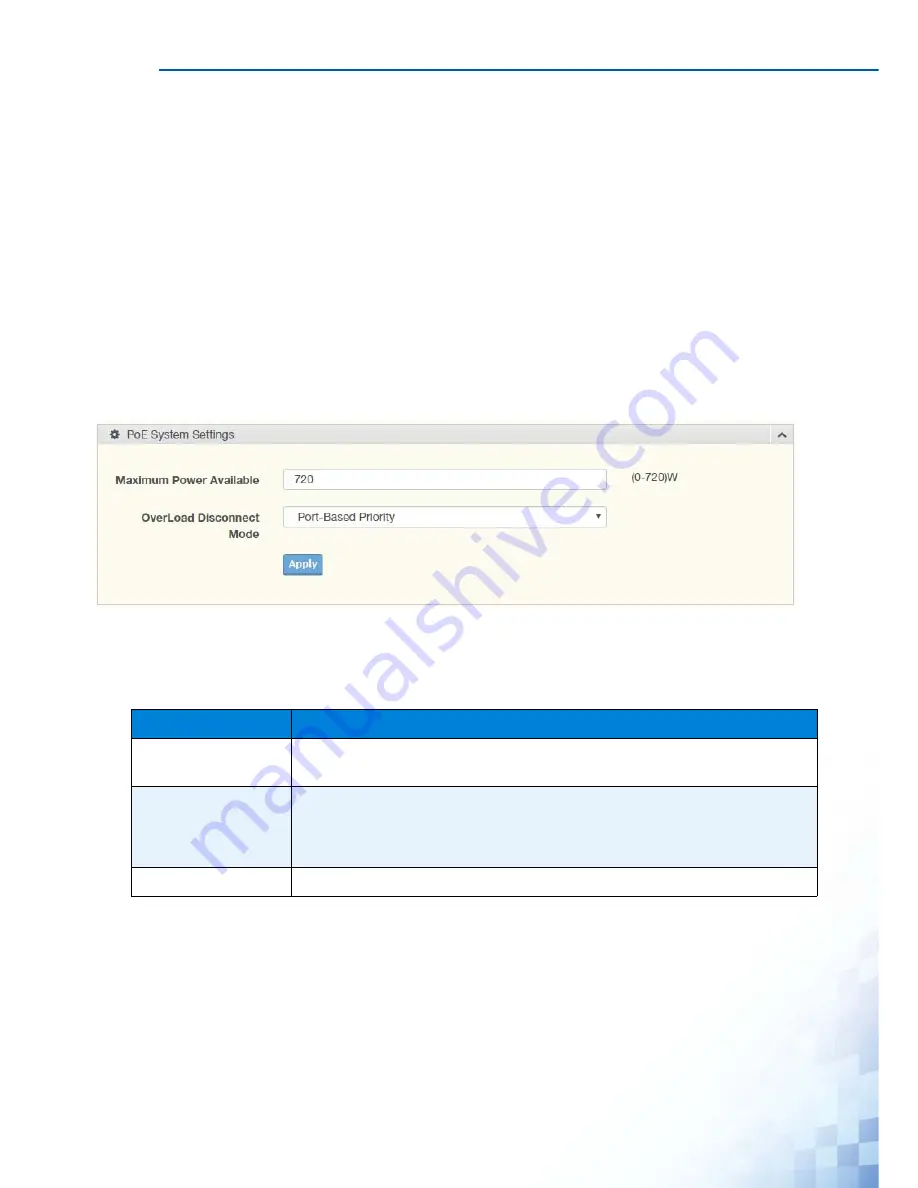
 PoE System Settings

The PoE System Settings page allows you to configure the overload disconnect and the 
maximum available wattage.

To access this page, click 

Management

 > 

Power Over Ethernet

 > 

PoE System Settings

.

Figure 4-89.

Management > Power Over Ethernet > PoE System Settings

The following table describes the items in the previous figure.

The ensuing table for 

PoE System Information

 settings are informational only: Firmware 

Version, Maximum Power Available, Actual Power Consumption and Overload Disconnect 
Type.

Table 4-87.

Management > Power Over Ethernet > PoE System Settings

Item

Description

Maximum Power 
Available

Select the value in Watts to set the maximum available power.

OverLoad 
Disconnect Mode

Click the drop-down menu to designate the overload mode:

Overload Port First: 

Port-Based Priority: 

Apply

Click 

Apply

 to save the values and update the screen.

Summary of Contents for EKI-7428G Series

Page 1: ...p LOOP Detection SYS PW1 PW2 P FAIL Reset EKI 7428G 4CI R M LINK ACT 28 27 26 25 28 27 26 25 2 PoE LINK ACT PoE LINK ACT 1 4 3 6 5 8 7 10 9 12 11 14 13 16 15 18 17 20 19 22 21 24 23 Ring Fail Temp LOO...

Page 2: ...ounting 9 2 5 Installing and Removing SFP Modules 10 2 5 1 Installing SFP Modules 11 2 5 2 Removing SFP Modules 12 2 6 Connecting the Switch to Ethernet Ports 13 2 6 1 RJ45 Ethernet Cable Wiring 13 2...

Page 3: ...in 25 Chapter 4 Managing Switch 4 1 Log In 27 4 2 Recommended Practices 28 4 2 1 Changing Default Password 28 4 3 Monitoring 29 4 3 1 Device Information 29 4 3 2 Logging Message 31 4 3 3 Port Monitori...

Page 4: ...7 1 Storm Control 82 4 7 2 Port Security 84 4 7 3 Protected Ports 85 4 7 4 DoS Prevention 86 4 7 5 Applications 89 4 7 6 802 1x 93 4 7 7 IP Security 95 4 8 QoS 97 4 8 1 General 97 4 8 2 QoS Basic Mod...

Page 5: ...ols 140 4 11 1 IXM 140 4 11 2 Backup Manager 141 4 11 3 Upgrade Manager 142 4 11 4 Dual Image 143 4 11 5 Save Configuration 143 4 11 6 User Account 144 4 11 7 Reset System 144 4 11 8 Reboot Device 145...

Page 6: ...erated in a commer cial environment This equipment generates uses and can radiate radio frequency energy and if not installed and used in accordance with the instruction manual may cause harmful inter...

Page 7: ...lant Do not leave this equipment in an environment where the storage temperature may go below 40 C 40 F or above 75 C 167 F this could damage the equipment The equipment should be in a controlled envi...

Page 8: ...r Conventions Copyright Copyright 2016 Advantech Inc All rights reserved No part of this publication may be reproduced adapted stored in a retrieval system translated into any language or transmit ted...

Page 9: ...manual is intended to guide professional installers in installing and configuring the 24G 4G Combo port L2 Managed Switch It includes technical specifications software util ity introduciton as we as p...

Page 10: ...ix...

Page 11: ...Chapter 1 Product Overview...

Page 12: ...43 6 x 259 2mm LED Display System LED SYS PWR1 PWR2 P Fail Loop detection R M Ring Fail Temp Port LED Speed Link Activity PoE only for EKI 7428G 4CPI Environment Operating Tem perature 40 C 70 C 40 F...

Page 13: ...ESD Level 3 EN 61000 4 3 RS Level 3 EN 61000 4 4 EFT Level 3 EN 61000 4 5 Surge Level 3 EN 61000 4 6 CS Level 3 EN 61000 4 8 Magnetic Field Level 3 Shock IEC 60068 2 27 Freefall IEC 60068 2 32 Vibrati...

Page 14: ...LED Panel on page 4 for further details 3 ETH port RJ45 ports x 4 4 SFP LEDs SFP link activity LEDs 5 ETH port Fiber ports x 4 6 PoE LED Orange 100M Green 1G 7 LNK ACT LED Link activity LED 8 ETH port...

Page 15: ...r PW2 is disconnected the LED lights Off When PW1 and PW2 is connected the LED is off 5 LOOP Detection Solid red When loop detected the LED lights Off No loop detected 6 R M Solid green Active when de...

Page 16: ...ply power Table 1 4 Rear View No Item Description 1 Ground terminal Screw terminal used to ground chassis 2 Console serial port Console cable port to COM port DB9 male on computer to RS232 managed swi...

Page 17: ...PRODUCT OVERVIEW 6 1 3 Dimensions Figure 1 4 EKI 7428G 4CPI Dimensions 438 22 41 35 426...

Page 18: ...uct package you have received should contain the following items If any of them are not included or damaged please contact your local vendor for support 1 x Industrial Ethernet Switch 1 x Rack Mount K...

Page 19: ...Chapter 2 Switch Installation...

Page 20: ...cting the system to its power source This unit is intended for installation in restricted access areas A restricted access area is defined as an area that can be accessed only through the use of a spe...

Page 21: ...d dam age to the switch make sure there is clerance at the top and bottom and around the exhaust vents 2 3 Environment and Enclosure Guidelines Review these environmental and enclosure guidelines befo...

Page 22: ...ys and how to connect to the network hock up the power cable and connect to the EKI 7428G Series 2 4 Verifying Switch Operation Before installing the device in a rack or on a wall power on the switch...

Page 23: ...pose that you are connecting devices I and II contrary to electrical signals optical signals do not require a cir cuit in order to transmit data Consequently one of the optical lines is used to transm...

Page 24: ...om of the transceiver 4 Insert the SFP transceiver into the slot until it clicks into place 5 Make sure the module is seated correctly before sliding the module into the slot A click sounds when it is...

Page 25: ...ers in the switch The fiber port is now setup 2 6 2 Removing SFP Modules To disconnect an LC connector use the following guidelines 1 Press down and hold the locking clips on the upper side of the opt...

Page 26: ...connected to the GND terminal For best performance use shielded cabling Shielded cabling may be used to provide further protection Figure 2 8 Ethernet Plug Connector Pin Position Maximum cable length...

Page 27: ...PC 9 pin D sub female and the switch s RJ45 RJ45 port a wired connection for management can be established Figure 2 9 Serial Console Cable Figure 2 10 DB 9 Pin Position Figure 2 11 Pin Assignment Tabl...

Page 28: ...idelines before wiring the device The Terminal Block CN1 is suitable for 12 24 AWG 3 31 0 205 mm2 Torque value 7 lb in The cross sectional area of the earthing conductors shall be at least 3 31 mm2 Ca...

Page 29: ...ce To avoid interference and signal degradation route power and communications wires through separate conduits Do not disconnect modules or cabling unless the power is first switched off The device on...

Page 30: ...nfigurations The power input 2 is used for wiring a redundant power configuration See the following for terminal block connector views Figure 2 15 Terminal Receptor Power Input Contacts To wire the po...

Page 31: ...ing up power redundancy connect PW2 in the same manner 3 Tighten the wire clamp screws to secure the DC wires in place Figure 2 16 Installing DC Wires in a Terminal Block 2 10 Reset Button Reset confi...

Page 32: ...SWITCH INSTALLATION 21...

Page 33: ...Chapter 3 Configuration Utility...

Page 34: ...explanation of how RSTP works is given in the Spanning Tree section The switch is capable of communicating with other SNMP capable devices on the network to exchange management information This stati...

Page 35: ...and subnet mask Refer to the quick start guide in Section 1 for how to initially access your switch To configure the switch for network access select Add Menu Address Here to reach the System Setting...

Page 36: ...ted Choose to enable auto negotiation or use fixed settings 100Mbps Fiber ports are Fixed speed only Speed Duplex Flow Control The managed switch accepts three local area network Ethernet Standards Th...

Page 37: ...is the IP address of the switch At the login prompt type cli for the username and admin for the password The switch will respond with Managed switch configuration CLI ready 3 3 Web Browser Configurat...

Page 38: ...er on the switch The following information guides you through the logging in process 1 Launch your web browser on the PC 2 In the browser s address bar type the switch s default IP address 192 168 1 1...

Page 39: ...Chapter 4 Managing Switch...

Page 40: ...ion is set to DHCP enabled You will need to make sure your network environment supports the switch setup before connecting it to the network 1 Launch your web browser on a computer 2 In the browser s...

Page 41: ...default password as soon as the device is functioning and setup correctly The following details the necessary steps to change the default password To change the password 1 Navigate to Tools User Accou...

Page 42: ...re 4 3 Monitoring Device Information The following table describes the items in the previous figure Table 4 1 Monitoring Device Information Item Description System Name Click Switch to enter the syste...

Page 43: ...ch Loader Date Displays the current loader build date of the switch Firmware Version Displays the current firmware version of the switch Firmware Date Displays the current firmware build date of the s...

Page 44: ...y level for the Logging Message Filter function Click the drop down menu to select the severity level target setting The level options are emerg Indicates system is unusable It is the highest level of...

Page 45: ...tPkts ifOutMulticastPkts and ifOutBroadcastPkts The ensuing table for Ether Like MIB Counters settings are informational only dot3StatsAlignmentErrors dot3StatsFCSErrors dot3StatsSingleCollisionFrames...

Page 46: ...click Monitoring Link Aggregation The ensuing table for Link Aggregation Group Status settings are informational only LAG Name Type Link State Active Member and Standby Member The ensuing table for LA...

Page 47: ...tics settings are informational only Insertions Deletions Drops and Age Outs The ensuing table for LLDP Port Statistics settings are informational only Port TX Frames Total RX Frames Total Discarded a...

Page 48: ...le for IGMP Statistics settings are informational only Total RX Valid RX Invalid RX Other RX Leave RX Report RX General Query RX Special Group Query RX Special Group Source Query RX Leave TX Report TX...

Page 49: ...atic DNS Server 2 Table 4 7 System IP Settings Item Description Mode Click the radio button to select the IP Address Setting mode Static or DHCP IP Address Enter a value to specify the IP address of t...

Page 50: ...The following table describes the items in the previous figure Table 4 8 System DHCP Client Option 82 Item Description Mode Click the radio button to enable or disable the DHCP Client Option 82 mode C...

Page 51: ...cess this page click System DHCP Auto Provision Figure 4 11 System DHCP Auto Provision The following table describes the items in the previous figure The ensuing table for DHCP Auto Provision Informat...

Page 52: ...y Auto Configuration IPv6 In Use Address IPv6 In Use Router IPv6 Static Address IPv6 Static Router and DHCPv6 Client Table 4 10 System IPv6 Settings Item Description Auto Configuration Select the radi...

Page 53: ...em Management VLAN Figure 4 13 System Management VLAN The following table describes the items in the previous figure The ensuing table for Management VLAN State are informational only Management VLAN...

Page 54: ...MANAGING SWITCH 41 4 4 6 System Time To access this page click System System Time Figure 4 14 System System Time...

Page 55: ...ort Enter the port on the server to which SNTP requests are to be sent Allowed range is 1 to 65535 default 123 Manual Time Click the drop down menus to set local date and time of the system Time Zone...

Page 56: ...Enable State Link Status Speed Duplex FlowCtrl Config and FlowCtrl Status Table 4 13 L2 Switching Port Configuration Item Description Port Click the drop down menu to select the port for the L2 Switch...

Page 57: ...irror Status settings are informational only Session ID Destination Port Ingress State Source TX Port and Source RX Port Table 4 14 L2 Switching Port Mirror Item Description Session ID Click the drop...

Page 58: ...n distribution of IP traffic across two or more links To access this page click L2 Switching Link Aggregation Load Balance Figure 4 17 L2 Switching Link Aggregation Load Balance The following table de...

Page 59: ...previous figure The ensuing table for LAG Management Information settings are informational only LAG Name Type Link State Active Member Standby Member Edit click to modify the settings and Clear clic...

Page 60: ...t Status settings are informational only LAG Description Port Type Enable State Link Status Speed Duplex FlowCtrl Config and FlowCtrl Status Table 4 17 L2 Switching Link Aggregation LAG Port Settings...

Page 61: ...2 Switching Link Aggregation LACP Priority Settings The following table describes the items in the previous figure The ensuing table for LACP Information settings are informational only System Priorit...

Page 62: ...on settings are informational only Port Name Priority Timeout and Mode Table 4 19 L2 Switching Link Aggregation LACP Port Settings Item Description Port Select Select a port for the LACP Port Settings...

Page 63: ...te VLAN listings and add a prefix name to an added entry To access this page click L2 Switching 802 1Q VLAN VLAN Management Figure 4 22 L2 Switching 802 1Q VLAN VLAN Management The following table des...

Page 64: ...unk8 PVID Enter the VLAN ID you want assigned to untagged or priority tagged frames received on this port The value ranges 1 to 4094 The default is 1 Accepted Type Click the radio button to specify wh...

Page 65: ...Port to VLAN The Port to VLAN page allows you to add a port to a VLAN and select the related parameters To access this page click L2 Switching 802 1Q VLAN Port to VLAN Figure 4 24 L2 Switching 802 1Q...

Page 66: ...ed port where both inner and outer VLANs are handled by the switch or switches so the attached machine sees ordinary Ethernet frames via a single tagged tunnel port where the outer VLAN only is handle...

Page 67: ...ings The following table describes the items in the previous figure The ensuing table for QinQ Global Information settings are informational only Outer VLAN Ethertype Table 4 23 L2 Switching Q in Q Gl...

Page 68: ...tings Item Description Port Select Enter the switch port part of VLAN configuration to configure the selection as a tunnel port Outer PVID Enter the Port VLAN ID PVID to assigned the native VLAN ID Al...

Page 69: ...tance of this timer exists for each GARP participant for each port Leave Time Enter a value to specify the time to wait after receiving an unregister request for a VLAN or multicast group before delet...

Page 70: ...age click L2 Switching GARP GVRP Settings Figure 4 28 L2 Switching GARP GVRP Settings The following table describes the items in the previous figure The ensuing table for GVRP Information settings are...

Page 71: ...ctive links or devices are detected To access this page click L2 Switching 802 3az EEE Figure 4 29 L2 Switching 802 3az EEE The following table describes the items in the previous figure The ensuing t...

Page 72: ...nown multicast request is received The options include Drop Flood or Router Port To access this page click L2 Switching Multicast Multicast Filtering Figure 4 30 L2 Switching Multicast Multicast Filte...

Page 73: ...P Snooping Version and IGMP Snooping V2 Report Suppression The ensuing table for IGMP Snooping Table settings are informational only Entry No VLAN ID IGMP Snooping Operation State Router Ports Auto Le...

Page 74: ...Switching Multicast IGMP Snooping IGMP Static Groups The following table describes the items in the previous figure Table 4 30 L2 Switching Multicast IGMP Snooping IGMP Querier Item Description VLAN I...

Page 75: ...ble the version v1 or v2 and the enabling disabling of the report suppression for the MLD querier which sends out periodic general MLD queries and are forwarded through all ports in the VLAN MLD Setti...

Page 76: ...35 L2 Switching Multicast MLD Snooping MLD Querier The following table describes the items in the previous figure The ensuing table for MLD Querier Status settings are informational only VLAN ID Queri...

Page 77: ...page click L2 Switching Multicast MLD Snooping Multicast Groups The ensuing table for Multicast Groups settings are informational only ID Group IP Address Member Ports Type and Life Sec Router Ports...

Page 78: ...L2 Switching Jumbo Frame Figure 4 37 L2 Switching Jumbo Frame The following table describes the items in the previous figure The ensuing table for Jumbo Frame Config settings are informational only J...

Page 79: ...able describes the items in the previous figure The ensuing table for STP Information settings are informational only STP BPDU Forward PathCost Method and Force Version Table 4 36 L2 Switching Spannin...

Page 80: ...nabled or Disabled to setup the admin profile for the STP port Path Cost 0 Auto Set the port s cost contribution For a root port the root path cost for the bridge 0 means Auto Edge Port Click the drop...

Page 81: ...ard Delay Max Age Tx Hold Count and Hello Time The ensuing table for STP Bridge Status settings are informational only Bridge Identifier Designated Root Bridge Root Path Cost Designated Bridge Root Po...

Page 82: ...s in the previous figure The ensuing table for STP Port Status settings are informational only Port Identifier Priority Port Id Path Cost Conf Oper Designated Root Bridge Root Path Cost Designated Bri...

Page 83: ...ibes the items in the previous figure The ensuing table for MST Configuration Identification Information settings are informational only Configuration Name and Revision Level Table 4 40 L2 Switching S...

Page 84: ...hing Spanning Tree MST Instance ID Settings The following table describes the items in the previous figure The ensuing table for MST Instance ID Information settings are informational only MSTI ID and...

Page 85: ...ted Root Bridge Root Path Cost Designated Bridge Root Port and TCNLast Topology Change The ensuing table for STP Port Status settings are informational only Port Identifier Priority Port Id Path Cost...

Page 86: ...isable the state of the X Ring settings To access this page click L2 Switching X Ring Elite X Ring Elite Settings Figure 4 45 L2 Switching X Ring Elite X Ring Elite Settings The following table descri...

Page 87: ...e ensuing table for Information settings are informational only Ring ID Role Port 1 Port 2 and Delete click to delete the desired Ring ID Table 4 44 L2 Switching X Ring Elite X Ring Elite Groups Item...

Page 88: ...re the status enabled or disabled of the function To access this page click L2 Switching X Ring Pro X Ring Pro Settings Figure 4 47 L2 Switching X Ring Pro X Ring Pro Settings The following table desc...

Page 89: ...Ring Pro X Ring Pro Groups X Ring Pro Groups Settings Item Description Ring ID Enter a number to specifies a ranging from 1 to 255 to identify a given X Ring Pro group Port 1 Click the drop down menu...

Page 90: ...which frames are transmitted and the delay before recovery To access this page click L2 Switching Loopback Detection Global Settings Figure 4 50 L2 Switching Loopback Detection Global Settings The fo...

Page 91: ...tection Port Settings The following table describes the items in the previous figure The ensuing table for Loopback Detection Port Information settings are informational only Port Enable State and Loo...

Page 92: ...Table Static MAC The following table describes the items in the previous figure The ensuing table for Static MAC Status settings are informational only No MAC Address VLAN Port and Delete click to del...

Page 93: ...e 4 53 MAC Address Table MAC Aging Time The following table describes the items in the previous figure The ensuing table for Dynamic Address Status settings are informational only Aging time Table 4 5...

Page 94: ...MAC Address VLAN Type Port and Add to Static MAC click to add the MAC address to static MAC address list Table 4 52 MAC Address Table Dynamic Forwarding Table Item Description Port Click the drop dow...

Page 95: ...al Settings Figure 4 55 Security Storm Control Global Settings The following table describes the items in the previous figure The ensuing table for Storm Control Global Information settings are inform...

Page 96: ...o designate the local port for the Storm Control function Port State Select Disabled or Enabled to define the port state Action Click the drop down menu to select the type of action to designate for t...

Page 97: ...ribes the items in the previous figure The ensuing table for Port Security Information settings are informational only Port Enabled FDB Learn Limit and Violation MAC Notification Table 4 55 Security P...

Page 98: ...rts The following table describes the items in the previous figure The ensuing table for Protected Ports Status settings are informational only Protected Ports and Unprotected Ports Table 4 56 Securit...

Page 99: ...bled or disabled the denial of service DoS Global Settings The DoS Global Settings page allows you to configure enabled or disabled the setting for each function To access this page click Security DoS...

Page 100: ...abled ICMP Fragments Click Enabled or Disabled to define the ICMP Fragments function IPv4 Ping Max Size Click Enabled or Disabled to set the maximum ping size for the IPv4 protocol IPv6 Ping Max Size...

Page 101: ...DoS Prevention DoS Port Settings Figure 4 60 Security DoS Prevention DoS Port Settings The following table describes the items in the previous figure The ensuing table for DoS Port Status settings are...

Page 102: ...plications TELNET The following table describes the items in the previous figure The ensuing table for Telnet Information settings are informational only Telnet Service and Current Telnet Sessions Cou...

Page 103: ...ty Applications SSH The following table describes the items in the previous figure The ensuing table for SSH Information settings are informational only SSH Table 4 60 Security Applications SSH Item D...

Page 104: ...able describes the items in the previous figure The ensuing table for HTTP Information settings are informational only HTTP Service and Session Timeout Table 4 61 Security Applications HTTP Item Descr...

Page 105: ...e following table describes the items in the previous figure The ensuing table for HTTPS Information settings are informational only HTTPS Service and Session Timeout Table 4 62 Security Applications...

Page 106: ...tional only 802 1x State Server IP Server Port Accounting Port Security Key and Reauth Period Table 4 63 Security 802 1x 802 1x Settings Item Description State Click Enabled or Disabled to set up 802...

Page 107: ...scribes the items in the previous figure The ensuing table for 802 1x Port Authorization settings are informational only Port and Port State Table 4 64 Security 802 1x 802 1x Port Configuration Item D...

Page 108: ...ty IP Security Global Settings Figure 4 67 Security IP Security Global Settings The following table describes the items in the previous figure The ensuing table for IP Security Status settings are inf...

Page 109: ...previous figure The ensuing table for IP Security Entry Information settings are informational only IP Address IP Mask Services and Action Table 4 66 Security IP Security Entry Settings Item Descript...

Page 110: ...manage the priority of the traffic delivery Implementing QoS in the network makes performance predictable and bandwidth utilization much more effective The QoS implementation is based on the prioritiz...

Page 111: ...oS Settings Item Description Port Enter the port number to associate with the QoS setting CoS Value Click the drop down menu to designate the Class of Service CoS value 0 to 7 for the Port entry Remar...

Page 112: ...importance weight of the queue relative to the other CoS queues WRR scheduling prevents low priority queues from being completely ignored during periods of high priority traffic The WRR scheduler sen...

Page 113: ...Mapping allows you to apply CoS mapping To access this page click QoS General CoS Mapping Figure 4 72 QoS General CoS Mapping of WRR Bandwidth Displays the allotted bandwidth for the queue entry in p...

Page 114: ...priority of the traffic The following table shows the DSCP to Queue map If these values are not appropriate for your network you need to modify them To access this page click QoS General DSCP Mapping...

Page 115: ...ows you to set IP Precedence mapping To access this page click QoS General IP Precedence Mapping Figure 4 74 QoS General IP Precedence Mapping Table 4 71 QoS General DSCP Mapping Item Description DSCP...

Page 116: ...bounds or throughput QoS mode supports two modes 802 1p and DSCP Global Settings The Global Settings page allows you to configure the trust mode to a port selection To access this page click QoS QoS...

Page 117: ...e describes the items in the previous figure The ensuing table for QoS Port Status settings are informational only Port and Trust State Table 4 73 QoS QoS Basic Mode Global Settings Item Description T...

Page 118: ...Control Figure 4 77 QoS Rate Limit Ingress Bandwidth Control The following table describes the items in the previous figure The ensuing table for Ingress Bandwidth Control Status settings are informat...

Page 119: ...e items in the previous figure The ensuing table for Egress Bandwidth Control Status settings are informational only Port and Egress Rate Limit Kbps Table 4 76 QoS Rate Limit Egress Bandwidth Control...

Page 120: ...Queue Status settings are informational only Queue Id and Egress Rate Limit Kbps Table 4 77 QoS Rate Limit Egress Queue Item Description Port Click the drop down menu to select the port to define the...

Page 121: ...System Settings The following table describes the items in the previous figure Table 4 78 Management LLDP LLDP System Settings Item Description Enabled Click Enabled or Disabled to set the Global Sett...

Page 122: ...or disabled of the selected port To access this page click Management LLDP LLDP Port Settings Figure 4 81 Management LLDP LLDP Port Settings LLDP Port Configuration The following table describes the...

Page 123: ...number associated with the TLV optional selection Optional TLV Select Click the drop down menu to select the LLDP optional TLVs to be carried multiple selections are allowed System Name To include sys...

Page 124: ...m Name System Description Capabilities Supported Capabilities Enabled and Port ID Subtype The ensuing table for Port Status settings are informational only Port Selected VLAN and Detail click the radi...

Page 125: ...cular device can be determined SNMP Settings The SNMP Settings page allows you to set the SNMP daemon state enabled or disabled To access this page click Management SNMP SNMP Settings Figure 4 85 Mana...

Page 126: ...s page click Management SNMP SNMP Community Figure 4 86 Management SNMP SNMP Community The following table describes the items in the previous figure The ensuing table for Community Status settings ar...

Page 127: ...create an SNMP profile Access Right Click read only or read write to define the access right for the profile Encrypted Click the option to set the encrypted option for the user setting Auth Protocol...

Page 128: ...nsuing table for Trap Host Status settings are informational only No IP Address Community Name Version and Delete click to delete the desired IP address Password Enter the characters to define the pas...

Page 129: ...agement Power Over Ethernet PoE System Settings Figure 4 89 Management Power Over Ethernet PoE System Settings The following table describes the items in the previous figure The ensuing table for PoE...

Page 130: ...gacy and Power Limit W Table 4 88 Management Power Over Ethernet PoE Port Settings Item Description Port Click the drop down menu to select a PoE port Enabled Select Enabled or Disabled to designate t...

Page 131: ...us Settings page allows you to configure the modbus function To access this page click Management TCP Modbus TCP Modbus Settings Figure 4 91 Management TCP Modbus TCP Modbus Settings The following tab...

Page 132: ...The following table describes the items in the previous figure The ensuing table for Status Information settings are informational only DHCP Server Service Table 4 90 Management DHCP Server Status Set...

Page 133: ...Clear click to clear IP pool Table 4 91 Management DHCP Server Global Settings Item Description Lease Time Type in the value designating the lease time 60 864000 in seconds for each setting lease Low...

Page 134: ...k to clear the settings Table 4 92 Management DHCP Server Port Settings Item Description Port Select Click the drop down menu to select a pre defined port to configure The suboptions are designated fo...

Page 135: ...igure Table 4 93 Management DHCP Server Option 82 Settings Item Description Entry Click the drop down menu to select an entry for the Option 82 setting Circuit ID Format Click the drop down menu to se...

Page 136: ...port 25 Global Settings The Global Settings page allows you to set the active profile for the SMTP client To access this page click Management SMTP Client Global Settings Figure 4 96 Management SMTP...

Page 137: ...ng table describes the items in the previous figure Table 4 95 Management SMTP Client Profile Settings Profile Settings Item Description Profile ID Click the drop down menu to select the identificatio...

Page 138: ...mational only Profile ID click the drop down menu to select a profile ID Server IP Server Port and Sender Mail Address Table 4 96 Management SMTP Client Profile Settings Profile Target Mail Settings I...

Page 139: ...following table describes the items in the previous figure Table 4 97 Management SMTP Client Sending Message Item Description Title Assign the title of the email The maximum length is 20 characters al...

Page 140: ...Management RMON Rmon Statistics The following table describes the items in the previous figure The ensuing table for Statistics Information settings are informational only Index Port Drop Events Octe...

Page 141: ...ckets Requested Interval Owner and Delete click to delete the desired index Table 4 99 Management RMON RMON History Item Description Index Enter the index entry 1 to 65535 to select the number of new...

Page 142: ...y Interval Enter a value 1 to 2147483647 to define the interval value for the Alarm Collection history Variable Enter the alarm variables to define the monitoring triggers Sample Type Enter the variab...

Page 143: ...us figure The ensuing table for Event Information settings are informational only Index Description Type Community Owner and Delete click to delete the desired index Table 4 101 Management RMON RMON E...

Page 144: ...e Diagnostics The following table describes the items in the previous figure The ensuing table for Test Result settings are informational only Port Channel A Cable Length A Channel B Cable Length B Ch...

Page 145: ...al value is blank The IP Address or host name you enter is not retained across a power cycle Host names are composed of series of labels concatenated with periods Each label must be between 1 and 63 c...

Page 146: ...d 100 packet loss Or PING 172 17 8 93 172 17 8 93 56 data bytes 64 bytes from 172 17 8 93 icmp_seq 0 ttl 128 time 0 0 ms 64 bytes from 172 17 8 93 icmp_seq 1 ttl 128 time 0 0 ms 64 bytes from 172 17 8...

Page 147: ...initial value is blank The IP Address or host name you enter is not retained across a power cycle Host names are composed of series of labels concatenated with dots Each label must be between 1 and 6...

Page 148: ...reply format of ping PING 2222 777 2222 777 56 data bytes 2222 777 ping statistics 4 packets transmitted 0 packets received 100 packet loss Or PING 2222 717 2222 717 56 data bytes 64 bytes from 2222 7...

Page 149: ...ce Click Enabled or Disabled to set the Logging Service status Apply Click Apply to save the values and update the screen Table 4 106 Diagnostics System Log Local Logging Item Description Target Enter...

Page 150: ...address Table 4 107 Diagnostics System Log System Log Server Item Description Server Address Enter the IP address of the log server Server Port Enter the Udp port number of the log server Severity Cli...

Page 151: ...lowing table describes the items in the previous figure The ensuing table for Diagnostic Alarm Information settings are informational only Diagnostic Alarm Table 4 108 Diagnostics DDM Item Description...

Page 152: ...rt Connector Speed VendorName VendorOui VendorPn VendorRev VendorSn and DateCode Table 4 109 Diagnostics DDM Item Description High Alarm Click Enabled or Disabled to set the alarm state High Warning C...

Page 153: ...The following table describes the items in the previous figure Table 4 110 Tools IXM Item Description Search Field Enter criteria to search the IXM information Displays the reference to the device nu...

Page 154: ...describes the items in the previous figure Table 4 111 Tools Backup Manager Item Description Backup Method Click the drop down menu to select the backup method TFTP or HTTP Server IP Enter the IP add...

Page 155: ...n the previous figure Table 4 112 Tools Upgrade Manager Item Description Upgrade Method Click the drop down menu to select the upgrade method TFTP or HTTP Server IP Enter the IP address of the upgrade...

Page 156: ...rmational only Flash Partition Image Name Image Size and Created Time 4 11 5 Save Configuration To access this page click Tools Save Configuration Click Save Configuration to FLASH to have configurati...

Page 157: ...to have all configuration parameters reset to their factory default values All changes that have been made will be lost even if you have issued a save Reset settings take effect after a system reboot...

Page 158: ...NG SWITCH 145 4 11 8 Reboot Device To access this page click Tools Reboot Device Click Reboot to reboot the switch Any configuration changes you have made since the last time you issued a save will be...

Page 159: ...Chapter 5 Troubleshooting...

Page 160: ...twisted pair connection does not exceed 100 meters 328 feet R replacement letter for Ohm symbol Diagnosing LED Indicators To assist in identifying problems the switch can be easily monitored through...

Reviews: